A kind of anti-electromagnetic method of tethered UAV and anti-electromagnetic structure of tethered UAV

An unmanned aerial vehicle, anti-electromagnetic technology, applied in the direction of tethered aircraft, unmanned aircraft, electromechanical devices, etc., can solve problems such as safety hazards, affecting the working efficiency of tethered drones, interference, etc.

Inactive Publication Date: 2018-07-10
西南无人机科技有限公司
View PDF5 Cites 0 Cited by
  • Summary
  • Abstract
  • Description
  • Claims
  • Application Information

AI Technical Summary

Problems solved by technology

[0002] Tethered UAVs have been widely used in many fields. When tethered UAVs are working, they need to be connected to UAVs in real time through transmission cables to supply power to UAVs, so as to drive UAVs to achieve various tasks in the air. Operation, the generator in the ground workstation generally provides 220V or 380V AC power, but before the power is transmitted to the drone through the transmission cable, the AC power generated by the generator needs to be converted into DC power through a switching power supply, and the 220V or 380V The voltage is transformed into a high voltage of 800~1000V, and then transmitted to the motor of the drone through the transmission cable, so as to drive the drone to fly or achieve other operations through the motor; however, it can be known from the principle of electromagnetics that due to the large voltage The amplitude increases, so a strong electromagnetic field will be generated in the process of power transmission. The electromagnetic waves in this electromagnetic field will greatly affect the UAV flying in the sky to receive the flight control signal from the ground workstation, thus causing unmanned The control of the drone is not sensitive, and it cannot complete the scheduled tasks. Its safety performance will also cause certain hidden dangers, which affects the work efficiency of the tethered drone. Therefore, it is necessary to solve the problems caused by electromagnetic field interference to improve the receiving sensitivity of the flight control signal. , to ensure that the tethered UAV can perform tasks normally

Method used


Image

  • A kind of anti-electromagnetic method of tethered UAV and anti-electromagnetic structure of tethered UAV
  • A kind of anti-electromagnetic method of tethered UAV and anti-electromagnetic structure of tethered UAV
  • A kind of anti-electromagnetic method of tethered UAV and anti-electromagnetic structure of tethered UAV

Examples


Embodiment Construction

[0031] In order to enable those skilled in the art to better understand the solutions of the present invention, the technical solutions in the embodiments of the present invention will be clearly and completely described below in conjunction with the drawings in the embodiments of the present invention. Obviously, the described embodiments are only It is a part of embodiments of the present invention, but not all embodiments. Based on the embodiments of the present invention, all other embodiments obtained by persons of ordinary skill in the art without making creative efforts belong to the protection scope of the present invention.

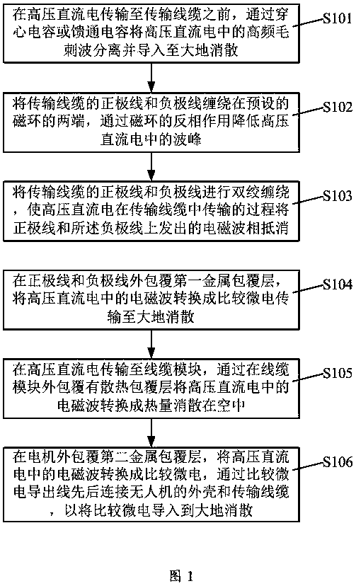
[0032] In order to solve the problem in the prior art that the tethered UAV cannot accurately receive the flight control signal of the ground workstation due to the interference of the electromagnetic field, resulting in the insensitive control of the UAV, the inability to complete the scheduled task, and the decline in safety, this application A...


PUM


Abstract

The invention discloses an anti-electromagnetic method for a tethered UAV, which includes: separating the high-frequency burr wave in the high-voltage direct current through a feed-through capacitor or a feed-through capacitor and leading it to the ground for dissipation; connecting the positive line of the transmission cable and the The negative wire is wound at both ends of the preset magnetic ring, and the peak in the high-voltage direct current is reduced by the anti-phase action of the magnetic ring; the positive and negative wires of the transmission cable are twisted in pairs, so that the high-voltage direct current can The process of transmission in the cable cancels the electromagnetic waves emitted by the positive line and the negative line; the positive line and the negative line are coated with the first metal cladding layer, and the electromagnetic wave in the high-voltage direct current is converted into a relatively small electric transmission to the earth Dissipation; the electromagnetic wave in the high-voltage direct current is converted into heat and dissipated in the air by covering the cable module with a heat dissipation coating layer; the second metal cladding layer is coated on the motor to convert the electromagnetic wave in the high-voltage direct current into a relatively small Electricity is used to introduce relatively micro-electricity into the earth for dissipation.

Description

technical field [0001] The invention relates to an anti-electromagnetic method for a tethered unmanned aerial vehicle and an anti-electromagnetic structure for a tethered unmanned aerial vehicle. Background technique [0002] Tethered UAVs have been widely used in many fields. When tethered UAVs are working, they need to be connected to UAVs in real time through transmission cables to supply power to UAVs, so as to drive UAVs to achieve various tasks in the air. Operation, the generator in the ground workstation generally provides 220V or 380V AC power, but before the power is transmitted to the drone through the transmission cable, the AC power generated by the generator needs to be converted into DC power through a switching power supply, and the 220V or 380V The voltage is transformed into a high voltage of 800~1000V, and then transmitted to the motor of the drone through the transmission cable, so as to drive the drone to fly or achieve other operations through the motor...

Claims


Application Information

Patent Timeline
Patent Type & Authority Patents(China)
IPC IPC(8): B64D45/00B64C39/02H02M1/44H02K5/04
CPCH02K5/04H02M1/44B64C39/022B64D45/00B64U2201/202
Inventor 崔文亮王立涛
Owner 西南无人机科技有限公司
Why Eureka
Try Eureka