Magnetron sputtering vacuum coating equipment

A vacuum coating and magnetron sputtering technology, applied in the field of magnetron sputtering vacuum coating equipment, can solve the problems of easy interference of discharge voltage, inconvenient popularization and application, and high production cost, so as to improve film thickness uniformity and coating effect, Improve the film deposition rate and the effect of good shielding effect

Inactive Publication Date: 2016-10-12
GUANGDONG ZHENHUA TECH CO LTD
View PDF5 Cites 6 Cited by
  • Summary
  • Abstract
  • Description
  • Claims
  • Application Information

AI Technical Summary

Problems solved by technology

[0003] First, when preparing transparent conductive films by DC sputtering metal oxides, it is easy to accumulate a large amount of charge on the surface of the target during the coating process, resulting in target poisoning. In addition, the deposition rate of DC sputtering transparent conductive films is still not fast enough, and the discharge The voltage is easily disturbed during the working process, which causes the discharge on the surface of the target to be unstable during the sputtering process, resulting in the uneven deposition of the film, the performance is not stable enough, and the transparent conductive film cannot be firmly attached to the surface of the substrate, etc.
[0004] Second, radio frequency sputtering equipment has high requirements on the process and shielding of vacuum coating equipment, the structure of coating equipment is cumbersome, the production cost is high, and it is not convenient for large-scale promotion and application

Method used


Image

  • Magnetron sputtering vacuum coating equipment
  • Magnetron sputtering vacuum coating equipment
  • Magnetron sputtering vacuum coating equipment

Examples


Embodiment Construction

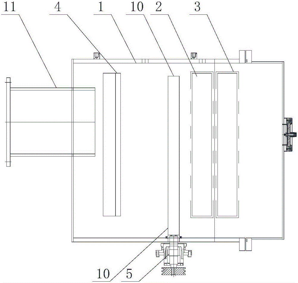
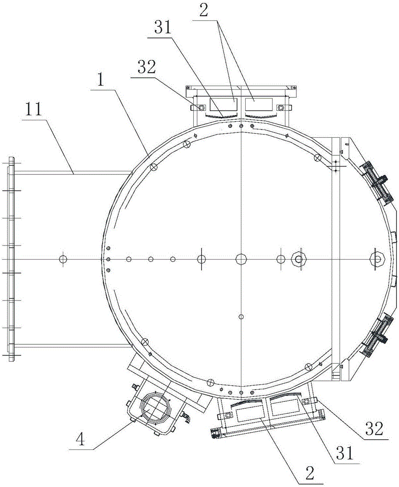
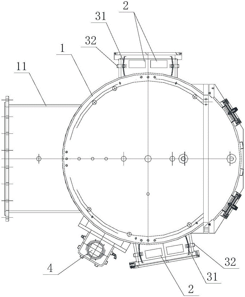
[0023] Such as Figure 1 to Figure 3 As shown, a kind of magnetron sputtering vacuum coating equipment described in the present invention includes a vacuum coating chamber 1 with a suction port 11 and a control power supply. Two groups of vertical plane twins are arranged on the side walls of the vacuum coating chamber 1. A magnetron target 2 , an open-close baffle device 3 is arranged around the planar twin magnetron target 2 , and a vertical planar ion source 4 is arranged on the side wall of the vacuum coating chamber 1 .

[0024] Such as figure 1 As shown, the planar twin magnetron target 2 includes two opposite vertical strip-shaped target heads, and the planar ion source 4 is a strip-shaped ion source standing upright on the side wall of the vacuum coating chamber 1 . The middle part in the vacuum coating chamber 1 is also provided with a rotary work platform 5 for installing the workpiece 10 to be coated and can drive the rotation of the workpiece 10 to be coated. sex...


PUM


Abstract

The invention belongs to the technical field of coating machine products, and particularly discloses magnetron sputtering vacuum coating equipment which comprises a vacuum coating chamber with an extraction opening, and a control power source. The side wall of the vacuum coating chamber is provided with a plurality of sets of vertical type planar twin magnetron targets, and an opening-closing type baffle device is arranged around the planar twin magnetron targets. A vertical type planar ion source is arranged in the vacuum coating chamber. According to the magnetron sputtering vacuum coating equipment, workpiece films are evenly deposited, the performance is stable, and the coating efficiency and effects of workpieces are greatly improved; and in addition, the equipment is simple, practical and low in manufacturing cost.

Description

technical field [0001] The invention belongs to the technical field of vacuum coating, in particular to a magnetron sputtering vacuum coating equipment. Background technique [0002] At present, transparent conductive films are widely used in the semiconductor and photovoltaic industries, and the preparation process of transparent conductive films mainly adopts the magnetron sputtering process, and the conventional ones are mainly DC sputtering and radio frequency sputtering. In the prior art, DC sputtering Sputtering and radio frequency sputtering technology has the following disadvantages: [0003] First, when preparing transparent conductive films by DC sputtering metal oxides, it is easy to accumulate a large amount of charge on the surface of the target during the coating process, resulting in target poisoning. In addition, the deposition rate of DC sputtering transparent conductive films is still not fast enough, and the discharge The voltage is easily disturbed durin...

Claims


Application Information

Patent Timeline
Patent Type & Authority Applications(China)
IPC IPC(8): C23C14/35
CPCC23C14/352C23C14/3407
Inventor 潘振强朱惠钦
Owner GUANGDONG ZHENHUA TECH CO LTD
Why Eureka
Try Eureka