Integrated annular assembling efficient excitation mixed-flow type hydraulic generator

A hydro-generator and mixed-flow technology, which is applied in the directions of hydroelectric power generation, reaction engine, engine function, etc., can solve the problems of poor cooling effect of cooling system, low excitation efficiency of excitation winding, and large force on transmission shaft and bearing. , to avoid the problem of bearing friction and energy consumption, good heat dissipation effect, and avoid the effect of eccentricity problem

Pending Publication Date: 2016-10-12
郭远军
View PDF0 Cites 0 Cited by
  • Summary
  • Abstract
  • Description
  • Claims
  • Application Information

AI Technical Summary

Problems solved by technology

[0006] The technical problems to be solved by the present invention are as follows: 1) The transmission shaft and bearing in the existing hydroelectric power generation device have relatively large losses due to the large force and high temperature generated by friction; 2) the generator of the existing hydroelectric power generation device Exciters and exciters will generate a lot of waste heat during work, and a special cooling system needs to be installed, and the cooling effect of the cooling system is not good, and it is easy to burn the core; 3) The high stable efficiency of the existing water turbine is only about 90%; 4) The existing hydro-generators are all customized machines for different terrains, and there are large differences in volume, so they cannot be mass-produced; High strength requirements; 6) The excitation efficiency of the excitation winding is low

Method used


Image

  • Integrated annular assembling efficient excitation mixed-flow type hydraulic generator
  • Integrated annular assembling efficient excitation mixed-flow type hydraulic generator
  • Integrated annular assembling efficient excitation mixed-flow type hydraulic generator

Examples


Embodiment Construction

[0031] The technical solutions in the embodiments of the present invention will be clearly and completely described below in conjunction with the accompanying drawings in the embodiments of the present invention; obviously, the described embodiments are only a part of the embodiments of the present invention, rather than all the embodiments. Based on the embodiments of the present invention, all other embodiments obtained by those of ordinary skill in the art without creative work shall fall within the protection scope of the present invention.

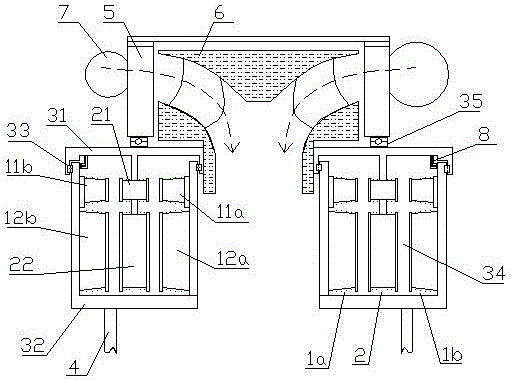
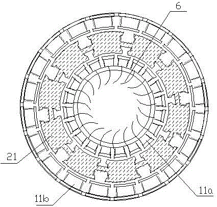
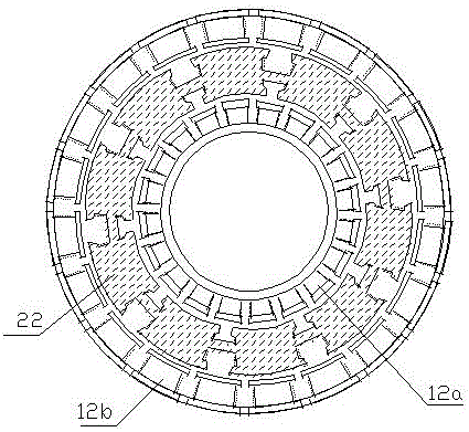
[0032] Option one (such as figure 1 , figure 2 with image 3 Shown): An integrated ring-mounted high-efficiency excitation mixed-flow turbine generator, including a first armature mechanism 1a, a second armature mechanism 1b, an excitation mechanism 2, a sealing cover mechanism 3, a draft tube 4, and a guide vane The mechanism 5, the runner 6 and the volute 7; the volute 7, the guide vane mechanism 5, the runner 6 and the draft tube 4 in...


PUM


Abstract

The invention discloses an integrated annular assembling efficient excitation mixed-flow type hydraulic generator which comprises a first armature mechanism, a second armature mechanism, an excitation mechanism, a sealing cover mechanism, a draft tube, a guide vane mechanism, a turning wheel and a volute. The volute, the guide vane mechanism, the turning wheel and the draft tube sequentially form a water flow channel; the sealing cover mechanism comprises a rotary cover and a fixed cover; the rotary cover and the fixed cover are coaxially connected through a sealing bearing to form a closed annular cavity; the first armature mechanism, the excitation mechanism and the second armature mechanism are sequentially and coaxially installed inside the annular cavity in parallel in an inner, middle and outer layer mode; the excitation mechanism is installed in the middle in the rotary cover; the first armature mechanism is installed on the inner-diameter side in the fixed cover; and the second armature mechanism is installed on the outer-diameter side inside the fixed cover. The integrated annular assembling efficient excitation mixed-flow type hydraulic generator is long in service life, low in building cost and production and management cost, high in excitation efficiency and high in water energy conversion efficiency.

Description

Technical field [0001] The invention relates to the field of hydropower equipment, and in particular to an integrated ring-mounted high-efficiency excitation mixed-flow hydroelectric generator. Background technique [0002] According to the working principle, hydraulic turbine power generation devices can be divided into two categories: impulse turbine and counterattack turbine. The runner of the impulse turbine rotates under the impact of the water flow. During the working process, the pressure of the water flow does not change, mainly due to the conversion of kinetic energy; the runner of the impact turbine rotates in the water by the reaction force of the water flow, and the pressure of the water flow during the working process Both energy and kinetic energy have changed, but mainly the conversion of pressure energy. [0003] The impulse turbine, because its working wheels only partially pass the water and part of the bucket is stressed, so this type of turbine requires a small...

Claims


Application Information

Patent Timeline
IPC IPC(8): F03B13/00F03B3/02F03B3/12F03B11/00H02K7/18H02K7/20H02K9/19
CPCF03B3/02F03B3/12F03B11/00F03B13/00F05B2220/7066F05B2260/20H02K7/1823H02K7/20H02K9/19Y02E10/20Y02P70/50
Inventor 郭远军
Owner 郭远军
Why Eureka
Try Eureka