
Centrifugal compressor

A centrifugal compressor and compressor technology, applied in the direction of electromechanical devices, mechanical equipment, engine components, etc., can solve the problems of centrifugal compressor efficiency decline, etc., to achieve the effect of improving efficiency and increasing bearing capacity

Active Publication Date: 2016-10-12
ZHEJIANG FUTENG FLUID TECH CO LTD
View PDF7 Cites 31 Cited by
  • Summary
  • Abstract
  • Description
  • Claims
  • Application Information

AI Technical Summary

Problems solved by technology

[0009] The object of the present invention is to provide a centrifugal compressor to solve the problem of efficiency drop caused by the miniaturization of the centrifugal compressor

Method used


Image

  • Centrifugal compressor
  • Centrifugal compressor
  • Centrifugal compressor

Examples


Embodiment 1

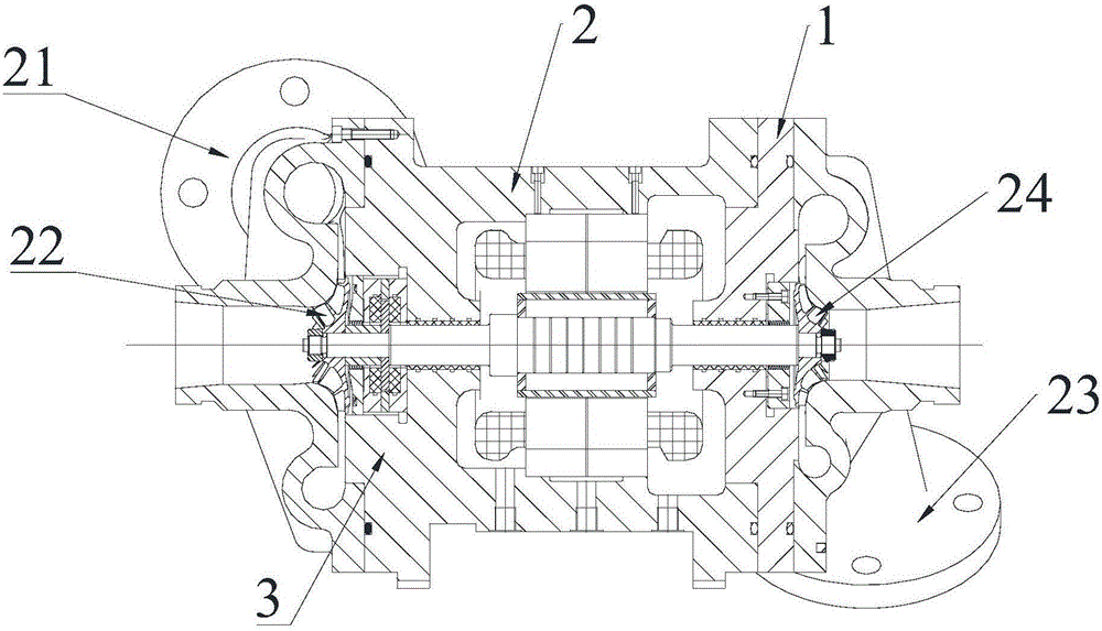
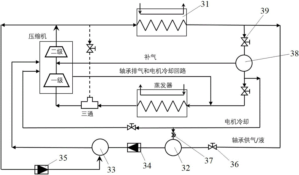
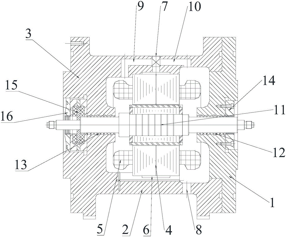
[0038] This embodiment provides a centrifugal compressor, especially a small centrifugal compressor, which includes a motor, a first-stage compressor and / or a second-stage compressor.

[0039] The motor drives the first-stage compressor and the second-stage compressor to operate. In this embodiment, the motor is a high-speed permanent magnet motor, and the high-speed permanent magnet motor uses a radial hydrostatic bearing to support the motor For the rotation of the rotor, an axial hydrostatic bearing is used to balance the axial force of the motor rotor; and the radial hydrostatic bearing and the axial hydrostatic bearing both use gas and liquid two-phase low-viscosity fluid as a lubricating medium.

[0040] In this embodiment, when it only includes a first-stage compressor, the centrifugal compressor is a single-stage compressor, and when it includes a first-stage compressor and a second-stage compressor, it is a two-stage compressor, At this time, the motor is a dual-outpu...


PUM


Abstract

The invention discloses a centrifugal compressor. The centrifugal compressor comprises a motor and a first-level compressor body. The motor drives the first-level compressor body to run. A motor rotor of the motor is supported by a radial hydrostatic bearing to rotate, and the axial force of the motor rotor is balanced through an axial hydrostatic bearing. Gas and liquid double-phase low-viscosity fluid is adopted as lubrication media for the radial hydrostatic bearing and the axial hydrostatic bearing. According to the centrifugal compressor, low-velocity liquid and gas double-phase refrigerant porous material hydrostatic air bearings are adopted as the radial hydrostatic bearing and the axial hydrostatic bearing supporting the motor rotor, the radial and axial waggling of the rotor is reduced, and therefore gaps and sealing gaps between the tops of blades of impellers and volutes are allowed to be reduced by a half, and accordingly the efficiency of the centrifugal compressor can be improved by 10% or above.

Description

technical field [0001] The invention relates to parts of a central air conditioner, in particular to a centrifugal compressor. Background technique [0002] Centrifugal compressors are widely used in large and medium-sized central air conditioners. They are composed of impellers, diffusers, volutes, motors, bearings, and bases. The rotating shaft of the motor is supported by bearings. The motor drives the impeller, and the high-speed rotating impeller increases the energy of the refrigerant gas. The diffuser converts the kinetic energy into pressure, and the volute collects the compressed gas along the periphery of the diffuser and discharges it from the centrifugal compressor. The centrifugal compressor impeller is a high-speed rotating part in the central air-conditioning system. Its reliability determines the reliability of the air-conditioning unit, and the reliability of the centrifugal compressor is determined by the reliability of the bearings supporting its rotor. ...

Claims


Application Information

Patent Timeline
Patent Type & Authority Applications(China)
IPC IPC(8): F04D17/10F04D25/06F04D29/051H02K5/04H02K5/20
CPCF04D17/10F04D25/0606F04D29/0513H02K5/04H02K5/20F04D29/057F16C32/0618F16C32/064F16C32/0662F16C32/0696F16C2360/44F04D17/122F04D25/06F04D29/063F04D29/051F04D29/056F04D29/286F04D29/4206F04D29/5806
Inventor 顾发华袁鹏宋节季裴俊谱冀伟星李飞
Owner ZHEJIANG FUTENG FLUID TECH CO LTD
Learn More