
Low-refractive-index optical coating material

An optical coating, low refractive index technology, applied in optics, optical components, sputtering coating, etc., can solve the problems of low refractive index coating materials, film cracking, film release, etc.

Inactive Publication Date: 2016-10-12
北京富兴凯永兴光电技术有限公司
View PDF5 Cites 5 Cited by
  • Summary
  • Abstract
  • Description
  • Claims
  • Application Information

AI Technical Summary

Problems solved by technology

This leads to low adhesion when silicon dioxide is used as a low refractive index optical coating material to form a film layer on the surface of plastic components, resulting in film cracking, film removal, etc.
At present, there is no single low-refractive index coating material in the domestic and foreign optical coating material market that can solve this problem well, and there is no similar patented technology

Method used


Image

  • Low-refractive-index optical coating material

Examples


Embodiment Construction

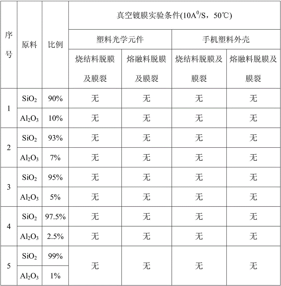
[0011] The raw material component proportioning of embodiment 1-5 is shown in table 1

[0012] According to the requirements of the present invention, carry out batching, mixing, granulation, sintering or melting by the ratio of silicon dioxide and aluminum oxide listed in Table 1, carry out the optical coating experiment with the optical coating material produced by this formula and process, The results are shown in Table 1. By batching, mixing, granulating, sintering and melting the mixture of silica and aluminum oxide listed in Table 1, coating experiments were carried out on optical plastic components and mobile phone plastic casings , the diameter of the vacuum coating machine is 1100, the temperature of the coating machine is 50°C, and the evaporation rate of the invented optical coating material is 10A 0 / S, the results are shown in Table 1.

[0013] Table 1

[0014]


PUM


Abstract

The invention discloses a low-refractive-index optical coating material. The optical coating material is prepared from silicon dioxide and an additive, and the additive is selected from one or more of aluminum oxide, magnesium oxide and yttrium oxide.

Description

technical field [0001] The invention relates to a low-refractive-index optical coating material, which belongs to the field of optical coating materials. Background technique [0002] In the field of optical coatings, silicon dioxide is the most commonly used low-refractive optical index coating material, but with the development of technology and applications, many traditional glass optical components are now mostly replaced by plastic components, such as camera lenses, etc., and some mobile phone casings Parts, which are themselves plastic components. Compared with glass optical components, these plastic components have low temperature resistance and large expansion coefficient. When coating plastic components, the substrate temperature in the coating machine is not as high as that of coated glass components. This leads to low adhesion when silicon dioxide is used as a low-refractive-index optical coating material to form a film on the surface of a plastic component, resu...

Claims


Application Information

Patent Timeline
IPC IPC(8): G02B1/00C23C14/08G02B1/10
CPCG02B1/00C23C14/08G02B1/10
Inventor 秦海波
Owner 北京富兴凯永兴光电技术有限公司
Learn More