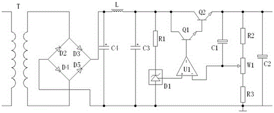
Voltage-stabilizing circuit by adopting LCpi-type filter and using bridge rectifier circuit for rectifier
A technology of bridge rectifier circuit and voltage stabilizing circuit, which is applied in the direction of converting DC power input to DC power output, converting AC power input to DC power output, electrical components, etc., and can solve the problem of reducing ripple coefficient and excessive ripple voltage Circuit and other problems, to achieve the effect of ensuring output voltage, voltage stability, and reasonable use
- Summary
- Abstract
- Description
- Claims
- Application Information
AI Technical Summary
Problems solved by technology
Method used
Image
Examples
Embodiment 1
[0024] The voltage stabilizing circuit rectified by a bridge rectifier circuit using LCπ filter solves the shortcomings of the existing technology that adopts bridge rectification and single capacitor filter after rectification output, the ripple voltage is too large and too much affects the follow-up circuit. , the use of LCπ-type filter for the first section filter processing after the rectified output can effectively reduce the ripple coefficient, provide high reliability voltage for subsequent processing, and use the voltage stabilization system designed based on controllable precision reference voltage regulation technology For voltage stabilization, such as figure 1 As shown, the following structure is specially set up: a bridge rectifier circuit, a filter circuit and a voltage stabilizing system with a controllable precision voltage stabilization function are provided, and a diode D2, a diode D3, a diode D4 and a diode D5 are arranged in the bridge rectifier circuit , t...
Embodiment 2
[0027] This embodiment is further optimized on the basis of the above-mentioned embodiments, further to better realize the present invention, such as figure 1As shown, the following configuration structure is adopted in particular: the controllable precision voltage stabilization system, a comparison circuit, a sampling circuit and an output filter circuit are arranged in the voltage stabilization system, and the controllable precision voltage stabilization source system is connected in parallel with the capacitor C3, The controllable precision voltage stabilizing source system is connected to a comparison circuit, the comparison circuit is connected to a sampling circuit, the sampling circuit is connected to an output filter circuit, and the output filter circuit is connected to a power supply circuit.
[0028] When designing and using, the controllable precision voltage stabilizing source system is connected in parallel with the capacitor C3, and the present invention uses a ...
Embodiment 3
[0030] This embodiment is further optimized on the basis of any of the above embodiments, such as figure 1 As shown, further in order to better realize the present invention, the voltage sampled by the sampling circuit can be compared with the reference voltage provided by the controllable precision regulated source system, thereby further adjusting the regulated power supply output by the output filter circuit, To obtain the required DC stabilized voltage output, the following configuration structure is particularly adopted: the comparison circuit is provided with a triode Q1, a triode Q2, an integrated operational amplifier U1 and a capacitor C1, the collector of the triode Q1 and the first capacitor of the capacitor C3 The base of the transistor Q1 is connected to the output terminal of the integrated operational amplifier U1, the emitter of the transistor Q1 is connected to the base of the transistor Q2, the collector of the transistor Q2 is connected to the first end of th...
PUM
 Abstract
Description
Claims
Application Information
 - R&D
- Intellectual Property
- Life Sciences
- Materials
- Tech Scout
- Unparalleled Data Quality
- Higher Quality Content
- 60% Fewer Hallucinations
Browse by: Latest US Patents, China's latest patents, Technical Efficacy Thesaurus, Application Domain, Technology Topic, Popular Technical Reports.
© 2025 PatSnap. All rights reserved.Legal|Privacy policy|Modern Slavery Act Transparency Statement|Sitemap|About US| Contact US: help@patsnap.com

