All functional glass sheet stacking and dismantling machine and glass sheet stacking and dismantling method

A full-featured, glass-based technology, applied to conveyor objects, transportation and packaging, lighting and heating equipment, etc., can solve the problems of inconvenient operation and maintenance of glass, and achieve the effects of easy operation and maintenance, improved precision and improved efficiency

Active Publication Date: 2016-10-19
深圳市天圣实业有限公司
7 Cites 15 Cited by

AI-Extracted Technical Summary

Problems solved by technology

[0004] The technical problem to be solved by the present invention is to provide a full-featured glass loading and unloading machine and a glass loading and unloading method, aiming at solving the problem that in the prior art, t...

Method used

Referring to Fig. 1, Fig. 2 and Fig. 4, two glass shelves 23 are all used for stacking the absorbed glass 300, and in the first direction K, the two glass shelves 23 are placed side by side and facing away from each other, and the glass shelves 23 It can move along the moving direction of the glass 300 on the rotating platform 22 . The bottom of the glass shelf 23 is provided with rollers (not shown) and a driving device (not shown) for driving the rollers to rotate. Glass frame 23 all comprises a vertical plate 232 and the transverse plate 233 that is connected at the bottom of vertical plate 232, and the outside ...

Abstract

The invention relates to the technical field of float glass and glass deep-processing, and provides an all functional glass sheet stacking and dismantling machine and a glass sheet stacking and dismantling method. The all functional glass sheet stacking and dismantling machine comprises a suction main engine and a piling bed. The suction main engine comprises a base, a pendulous device, a sucker device, and a rotating device. The pendulous device comprises a swing frame and a first rotating shaft used to drive the swing frame to swing between a glass production line and the piling bed. The rotating device comprises a second rotating shaft used to drive the sucker device to rotate. Compared with the prior art, using the global function glass sheet up-down machine, stacked glass is easy to operate and maintain. The glass sheet stacking and dismantling method comprises: according to purposes of glass, selecting a suction surface and stacking and dismantling the glass sheets, after the suction main engine is used for putting or taking down one glass sheet, a glass frame with the glass sheets moving a trip, after the glass frame is full or empty, automatically switching a vacant glass frame. Thus, efficiency of sheet up-down is greatly improved.

Application Domain

Technology Topic

EngineeringGlobal function +6

Image

  • All functional glass sheet stacking and dismantling machine and glass sheet stacking and dismantling method
  • All functional glass sheet stacking and dismantling machine and glass sheet stacking and dismantling method
  • All functional glass sheet stacking and dismantling machine and glass sheet stacking and dismantling method

Examples

  • Experimental program(2)

Example Embodiment

[0033] Embodiment one
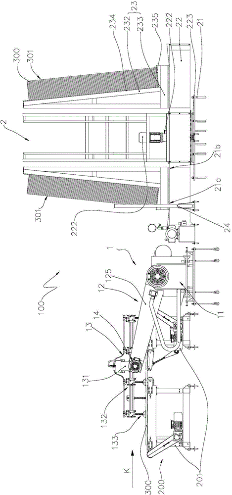
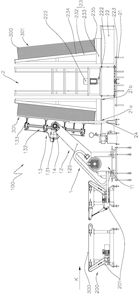
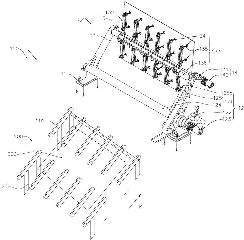
[0034] like Figure 1 to Figure 4 Shown is a preferred embodiment provided by the present invention.
[0035] The full-featured glass loading and unloading machine 100 provided by the present embodiment includes a glass plate 300 (hereinafter, for the purpose of simplification, the term is abbreviated as "glass production line 200") for the float glass production line 200 (hereinafter, for the sake of simplicity). For the sake of simplification, this term is simplified as "glass 300") suction host 1 for suction and stacking platform 2 for placing glass 300 to be sucked. The suction host 1 includes a base 11 , a swinging device 12 , a suction cup device 13 and a rotating device 14 . The swing device 12 is supported by the base 11, and the swing device 12 includes a swing frame 121, a first rotating shaft 122 fixedly connected to the side of the swing frame 121 near the base 11, and a first rotating shaft 122 for driving to rotate so that the swing frame 121 The side away from the base 11 is a first power member 123 that swings between the glass production line 200 and the stacking platform 2 around the side of the swing frame 121 close to the base 11 . The suction cup device 13 is used for suctioning the glass 300 . The rotating device 14 includes a second rotating shaft 141 fixedly connected to the suction cup device 13 and a second power member 142 for rotating the second rotating shaft 141. The shafts 122 are parallel.
[0036] The full-function glass loading and unloading machine 100 described above can select the suction surface of the glass 300 according to the application of the glass 300, and the stacked glass 300 is easy to operate and maintain, and has high safety and reliability.
[0037] For the convenience of description, the "left", "right", "upper" and "lower" referred to below are consistent with the left, right, up and down directions of the drawings themselves, but do not limit the structure of the present invention.
[0038] The full-function glass loading and unloading machine 100 is used to absorb and unload the glass 300 on the glass production line 200, see Figure 1 to Figure 4 , the full-featured glass loading and unloading machine 100 includes a suction host 1 and a stacking platform 2 . During manufacture, the glass 300 on the glass production line 200 moves along a first direction K (the first direction K is the moving direction of the glass 300 on the glass production line 200 ).
[0039] The cold end of the glass production line 200 has a plurality of roller tables 201, each roller table 201 is equipped with rollers for transporting the glass 300, between the outermost roller table 201 and the adjacent roller table 201 There is a certain matching distance between them. The glass 300 of the glass production line 200 has a first surface 301 facing upward and a second surface 302 opposite to the first surface 301 .
[0040]The suction host 1 is used to suction the glass 300 on the glass production line 200 and move the glass 300 to the stacking platform 2 after suction, see Figure 1 to Figure 4 , which includes a base 11 , a swing device 12 , a suction cup device 13 and a rotation device 14 .
[0041] In this embodiment, the base 11 is used to place and support the swing device 12 , the sucker device 13 and the rotation device 14 .
[0042] see Figure 1 to Figure 4 , the swing device 12 includes a swing frame 121, a first rotating shaft 122 for driving the swing frame 121 to rotate, and a first power member 123 for controlling the rotation of the first rotating shaft 122 (it should be noted that the first rotating shaft 122 and the first power Part 123 can be connected by a coupling, and can also be connected by means of a transmission gear or a transmission chain), the first power part 123 is a geared motor (the geared motor is a modular combination of a gear box and a motor, of course It can also be formed by split connection). The swing frame 121 includes a turning beam 124 and two turning arms 125 connected to two ends of the turning beam 124 . Two overturning rotating arms 125, its spacing should be greater than the width of the outermost roller table 201, two overturning rotating arms 125 are arranged in parallel and all extend along the length direction perpendicular to the overturning beam 124, two overturning rotating arms 125 and the overturning The beam 124 is fixedly connected by welding or screws and can rotate together with the turning arm 125 . The overturning beam 124 is roughly cylindrical, it is placed horizontally between the glass production line 200 and the stacking platform 2 , and extends along a direction perpendicular to the first direction K in the same horizontal plane. The first rotating shaft 122 is fixedly connected to the turning beam 124, and the two are basically arranged coaxially. Through the control of the first power member 123, the first rotating shaft 122 is rotated, and then the turning beam 124 is driven to rotate within a certain angle to realize the swing frame. 121 swings back and forth between the glass production line 200 and the stacking platform 2 around the first rotating shaft 122 .
[0043] Of course, the swing frame 121 can also be composed of a turning arm 125 and a turning beam 124. The turning arm 125 is fixedly connected to the middle part of the turning beam 124. There is a notch in the middle part of the top surface. When the swing frame 121 swings to the glass production line 200 to absorb the glass 300, the notch allows the turning arm 125 to extend downward into the roller table 201.
[0044] see Figure 1 to Figure 4 , the sucker device 13 includes a sucker frame 132 with a rotating beam 131, the rotating beam 131 is approximately cylindrical, and the two ends of the rotating beam 131 are rotatably connected with two turning arms 125 respectively, and the sucker frame 132 is equipped with a The suction assembly 133 for suctioning the glass 300 . The suction assembly 133 includes a plurality of suction cups 134 , a suction rod 135 corresponding to the plurality of suction cups 134 , and a compression cylinder 136 . When sucking the glass 300, move the sucker device 13 to the glass production line 200 and gradually approach the glass 300 to be sucked. When the sucker 134 is in contact with the surface of the glass 300, the compressed air cylinder 136 pumps the gas, and between the sucker 134 and the surface of the glass 300 A vacuum suction force is formed, so that the glass 300 is tightly attached to the suction cup holder 132 of the suction cup device 13 . When the suction cup device 13 moves to the stacking platform 2, the compressed air cylinder 136 is exhausted, and the suction cup 134 is separated from the surface of the glass 300.
[0045] see Figure 1 to Figure 4 , the rotating device 14, which includes a second rotating shaft 141 and a second power member 142 that controls the rotation of the second rotating shaft 141 (it should be noted that the second rotating shaft 141 and the second power member 142 may be connected through a coupling, or It may be transmission connection through transmission gears or transmission chains), the second power member 142 is a steering motor, the second rotating shaft 141 is fixedly connected to the rotating beam 131, and the two are basically coaxially arranged. It should be noted that the rotating beam 131 is substantially parallel to the axis of the turning beam 124 (that is, the second rotating shaft 141 is arranged parallel to the first rotating shaft 122), and there is a certain distance between the two turning arms 125. The second power member 142 and the first power member 123 are on the outside of the same turning arm 125 . Through the control of the second power member 142, the second rotating shaft 141 is rotated, and then the suction cup holder 132 is rotated between the two turning arms 125 around the axis of the rotating beam 131, and the rotation angle is between 0-360 degrees.
[0046] Select the suction surface according to the use of glass 300: see figure 1 and figure 2 , figure 1 and figure 2 Shown in is the situation that the full-function glass loading and unloading machine 100 provided by the present invention performs loading and unloading from the top of the glass 300 to be sucked. Part 142 makes the suction cup frame 132 rotate clockwise at a certain angle, and starts the first power part 123 to make the swing frame 121 swing to the top of the glass 300 to be sucked on the glass production line 200. At this time, the suction cup 134 on the suction cup frame 132 is set downward. After the suction cup device 13 moves down to hold the first surface 301 of the glass 300, the first power member 123 is reversely rotated to lift the sucked glass 300 together with the suction cup device 13, and at the same time controls the second power part 142 to reverse direction. Rotate at a certain angle, and move to the stacking platform 2 for stacking, so as to form the first surface 301 of the glass 300 to be stacked sequentially outward;
[0047] see Figure 4 , Figure 4 Shown in is the full-featured glass loading and unloading machine 100 provided by the present invention to perform unloading and unloading from the bottom of the glass 300 to be sucked. , make the suction cup frame 132 rotate counterclockwise at a certain angle, start the first power part 123 to make the swing frame 121 swing to the bottom of the glass 300 to be sucked on the glass production line 200, at this time, the suction cup 134 on the suction cup frame 132 is set upwards, and the suction cup device 13 After moving upwards to hold the second surface 302 of the glass 300, reversely rotate the first power part 123 to lift the sucked glass 300 together with the sucker device 13, and control the second power part 142 to rotate in reverse for a relatively With a small rotation angle, the second surface 302 of the glass 300 is formed to be stacked sequentially outward.
[0048] In order to adapt to the suction of glass 300 of different sizes, see image 3 , a plurality of adjusting mounting holes 125a that are installed in cooperation with the rotating crossbeam 131 are opened on the two turning arms 125, and the adjusting installing holes 125a on each turning arm 125 are arranged side by side and alternately, and one of the turning arms 125 is turned over and rotated The multiple adjustment mounting holes 125a on the arm 125 correspond to the multiple adjustment mounting holes 125a on the other turning arm 125 one by one. When the area of ​​the glass 300 to be produced is large, the rotating beam 131 can be installed in the adjusting mounting hole 125a near the outer end; In this way, when picking up the glass 300 with a small size, the torque can be reduced and the loss can be saved.
[0049] The stacking platform 2 includes a base 21 , a rotating platform 22 and two glass shelves 23 .
[0050] The base 21 is used for carrying the rotating platform 22 and the glass frame 23 , and the base 21 is roughly located in the first direction K.
[0051] see figure 1 , figure 2 and Figure 4 , the rotating platform 22 is roughly in the shape of a disk, and is rotatably mounted on the base 21. A third rotating shaft 221 for driving the rotating platform 22 and controlling the third rotating shaft 221 are arranged between the rotating platform 22 and the base 21. A rotating third motor 222 , the third motor 222 may be a steering motor, the third rotating shaft 221 is arranged vertically, and the glass shelf 23 is placed on the rotating platform 22 . The bottom of the rotating platform 22 is fixedly equipped with a rotating ring gear 223. The rotating ring gear 223 has an internal ring gear. The bottom of the rotating ring gear 223 is installed on the base 21 through a thrust bearing (not shown). A transmission assembly (not shown) is installed, and the transmission assembly includes a driving gear connected to the third rotating shaft 221 and a driven gear meshed with the driving gear, the driven gear meshes with the rotating ring gear 223, and the third rotating shaft 221 rotates , the rotating ring gear 223 is rotated through the transmission assembly, so that the rotating platform 22 is rotated.
[0052] see figure 1 , figure 2 and Figure 4 , two glass racks 23, both used to stack the glass 300 to be sucked, in the first direction K, the two glass racks 23 are placed side by side with their backs facing outwards, and the glass racks 23 can be moved along the moving direction of the glass 300 on the rotating platform 22 move. The bottom of the glass shelf 23 is provided with rollers (not shown) and a driving device (not shown) for driving the rollers to rotate. Glass frame 23 all comprises a vertical plate 232 and the transverse plate 233 that is connected at the bottom of vertical plate 232, and the outside of vertical plate 232 has the first slope 234 that extends downwards and outwards obliquely from this vertical plate 232 top face, and the horizontal plate 233 The top surface has a second slope 235 extending outward and upward from the first slope 234 , and the first slope 234 is perpendicular to the second slope 235 . The angle between the second slope 235 and the horizontal plane is between 10-30 degrees, so that the glass 300 can be basically stood upright on the glass frame 23, avoiding pressure loss and cracking caused by excessive pressure between the glasses 300, and is not easy Drops down for easy storage.
[0053] In order to improve the efficiency of loading and unloading sheets, the stacker 2 further includes a first position detection device 24 and a second position detection device (not shown). see figure 1 , figure 2 and Figure 4 , the first position detection device 24 and the second position detection device are installed on one side of the base 21 respectively, and arranged sequentially in the first direction K, and the two position detection devices may be position sensors or inductive switches. The first position detection device 24 defines a first detection part 21a at a position close to the edge of the rotary platform 22 , and the second position detection device defines a second detection part 21b at a position close to the center of the rotary platform 22 . When the glass 300 placed on the glass shelf 23 is projected on the rotating platform 22 and is located in the first detection portion 21a, the first position detection device 24 controls the driving device to move the glass shelf 23 to the center of the rotating platform 22 by approximately one glass. 300 thickness, and stop the glass shelf 23 after the outer edge of the glass 300 (when there are multiple pieces of glass 300 stacked on the glass shelf 23, refers to the outermost glass 300) leaves the first detection position 21a of the mobile. When the glass shelf 23 moves to the second detection position 21b, the glass 300 stacked on the surface glass shelf 23 has reached the maximum value, so the second position detection device controls the rotating platform 22 to rotate horizontally by 180 degrees after detecting the above situation. degree, the glass shelf 23 filled with glass 300 is replaced with another empty glass shelf 23, and the glass shelf 23 filled with glass 300 is removed to store the glass 300. In this way, when the stacked glasses 300 are stacked each time, the glass frame 23 for placing the glass 300 moves a stroke. Therefore, the swing range of the swing frame 121 of the swing device 12 is the same every time, which not only improves the stacking efficiency, but also improves the stacking efficiency. The placement accuracy of the stacked glass 300 is improved, and the replacement of the glass rack 23 is facilitated by rotating the platform 22, thereby greatly improving work efficiency.
[0054] Of course, when the rotating platform 22 is relatively large, the number of glass shelves 23 can also be increased or decreased according to needs, for example, four glass shelves 23 are used, which are respectively placed at 90 degrees around the axis of the third rotating shaft 221 .

Example Embodiment

[0055] Embodiment two
[0056] Combine below Figure 5 , only the differences from Embodiment 1 will be described in detail.
[0057]The walking and turning platform 25 is used for placing the sucked glass 300 horizontally. The walking overturning platform 25 includes a moving base 251 , a placing plate 252 arranged on the moving base 251 for loading and stacking the glass to be absorbed 300 , and an overturning mechanism 253 that drives the placing plate 252 to turn outward. The placing plate 252 is L-shaped, and under the action of the turning mechanism 253 , it can rotate by 90°. The right end of the placing plate 252 is pivotally connected on the moving seat 251 by a horizontal rotating shaft. The walking and turning platform 25 also includes a second roller 254 arranged at the bottom of the moving base 251 and a third power member 255 that drives the second roller 254 to move along the first direction K. The third power member 255 is a servo motor or a variable frequency motor. After the glass 300 is stacked on the walking and turning platform 25, the walking turning platform 25 will move the glass 300 placed on it into the warehouse for storage. When necessary, the turning mechanism 253 can be used to raise a certain angle for storage, which improves the storage efficiency. .
[0058] Of course, the walking turning platform 25 can also be placed on the rotating platform 22, as shown in the first embodiment, two or more walking turning platforms 25 are set and arranged at intervals around the circumferential direction of the turning platform 22, and one of them walking turns over After the platform 25 is full of glass 300, the rotating platform 22 rotates a certain angle, and moves out the walking turning platform 25 full of glass 300 and moves into the vacant walking turning platform 25 simultaneously.
[0059] The glass 300 two-way vertical stacking method provided by the present invention includes the following steps:
[0060] (1) According to the purpose of the glass 300, the suction surface is selected for stacking. When the first surface 301 of the glass 300 needs to be stacked outward, the suction cup device 13 is moved to the glass 300 to be sucked in the glass production line 200 by the swing device 12 Above, the suction cup device 13 is controlled by the rotating device 14 to rotate downward so that the suction cup 134 on the suction cup holder 132 faces the first surface 301 of the glass 300 to be sucked; or when the second surface 302 of the glass 300 needs to be stacked When releasing, the suction cup device 13 is moved to the bottom of the glass 300 to be sucked in the glass production line 200 by the swing device 12, and the suction cup device 13 is controlled by the rotating device 14 to rotate upward so that the suction cup 134 on the suction cup holder 132 faces the glass 300 to be sucked. The second surface 302 of . After the glass 300 is sucked by the suction cup device 13 , the sucked glass 300 is lifted together with the suction cup device 13 by the swing device 12 and moved toward the glass shelf 23 .
[0061] (2) After the glass 300 to be sucked is placed obliquely on the glass shelf 23, the suction cup device 13 is separated from the piece of glass 300, and returns to the glass production line 200 under the action of the swing device 12 to wait for grabbing the next glass 300;
[0062] (3) When the glass 300 is placed on the glass shelf 23 and is in the first detection position 21a, the first position detection device 24 controls the glass shelf 23 to move toward the center of the rotating platform 22 (approximately a stroke of glass 300 thickness) , stop after the projection of the outer edge of the glass 300 does not intersect with the first detection site 21a); ​​in the first direction K, a first detection site 21a is defined above the rotary platform 22 near its edge, close to the rotary platform 22, there is a second detection position 21b in the center; when the glass shelf 23 close to the glass production line 200 is at the initial position, the vertical plate 232 of the glass shelf 23 is approximately close to the first detection position 21a, and the first piece of glass 300 is stacked to After the glass shelf 23 is on, the first position detection device 24 controls the glass shelf 23 to move to the center of the rotating platform 22 (that is, the second detection position 21b) approximately a glass 300 thickness stroke (like this, absorbing the swing range of the main frame 1 and The position of the glass 300 docked during stacking remains basically unchanged), the outer edge of the piece of glass 300 is approximately close to the first detection position 21a after the movement of the glass shelf 23 stops, and the above steps are repeated after the next glass 300 is placed.
[0063] (4) When the glass shelf 23 moves to the second detection position 21b, it means that the glass shelf 23 is full, and the second position detection device controls the rotating platform 22 to rotate horizontally by 180 degrees (the specific angle can be determined according to the glass shelf 23 The quantity is adjusted) to switch the positions of the two glass shelves 23 on the rotating platform 22, and store the glass shelves 23 full of glass 300 after switching.

PUM

no PUM

Description & Claims & Application Information

We can also present the details of the Description, Claims and Application information to help users get a comprehensive understanding of the technical details of the patent, such as background art, summary of invention, brief description of drawings, description of embodiments, and other original content. On the other hand, users can also determine the specific scope of protection of the technology through the list of claims; as well as understand the changes in the life cycle of the technology with the presentation of the patent timeline. Login to view more.

Similar technology patents

Classification and recommendation of technical efficacy words

  • Easy to operate and maintain
  • Improve safety and reliability

Power supply device for transformer substation

Owner:HUAIBEI POWER SUPPLY COMPANY OF STATE GRID ANHUI ELECTRIC POWER +1

Electric power supply device with electric shock protection function

Owner:国网安徽省电力有限公司铜陵市义安区供电公司
Why Eureka
Try Eureka