Organic light emitting structure, organic light emitting device possessing the structure and panel

A technology of organic light-emitting devices and light-emitting structures, which is applied in the manufacture of electric solid-state devices, semiconductor devices, and semiconductor/solid-state devices.

Inactive Publication Date: 2016-10-19
EVERDISPLAY OPTRONICS (SHANGHAI) CO LTD
View PDF7 Cites 21 Cited by
  • Summary
  • Abstract
  • Description
  • Claims
  • Application Information

AI Technical Summary

Problems solved by technology

[0005] Improving the light extraction efficiency is to extract the light emitted inside the OLED as much as possible. However, in the existing organic light-emitting structure, light will be lost when it comes out from the side, for example, the pixel definition layer (PDL) on the side The light transmittance of the position is only 80-85%, and the transmittance of the cathode on the side PDL is only 40-50%, so a considerable part of the emitted light passes through the layers such as the PDL and the cathode on the side wasted again

Method used


Image

  • Organic light emitting structure, organic light emitting device possessing the structure and panel
  • Organic light emitting structure, organic light emitting device possessing the structure and panel
  • Organic light emitting structure, organic light emitting device possessing the structure and panel

Examples


Embodiment 1

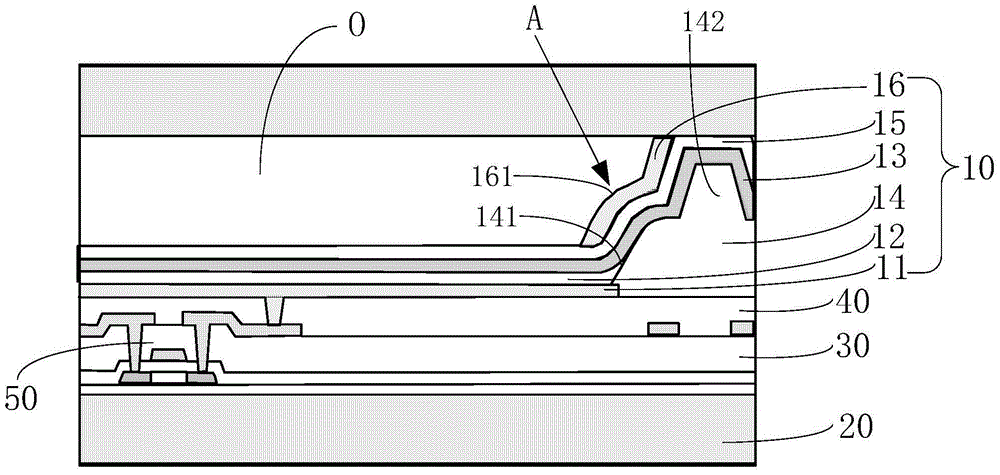
[0036] see figure 1 , is a partial cross-sectional schematic diagram of the organic light-emitting device of Example 1 of the present invention. The organic light-emitting device includes a substrate 20 , an insulating layer 30 formed on the substrate 20 , a thin film transistor 50 formed on the substrate 20 , a protective layer 40 covering the thin film transistor 50 , and an organic layer formed on the protective layer 40 . Light emitting structure 10 . In this embodiment, the protective layer 40 is a flat layer, but the present invention is not limited thereto, for example, the protective layer may also have a concave structure.

[0037] The organic light emitting structure 10 includes a first electrode layer 11 electrically connected to the thin film transistor 50 , an organic light emitting layer 12 located on the first electrode layer 11 , a second electrode layer 13 located on the organic light emitting layer 12 , and a pixel definition layer 14 , the light extraction...

Embodiment 2

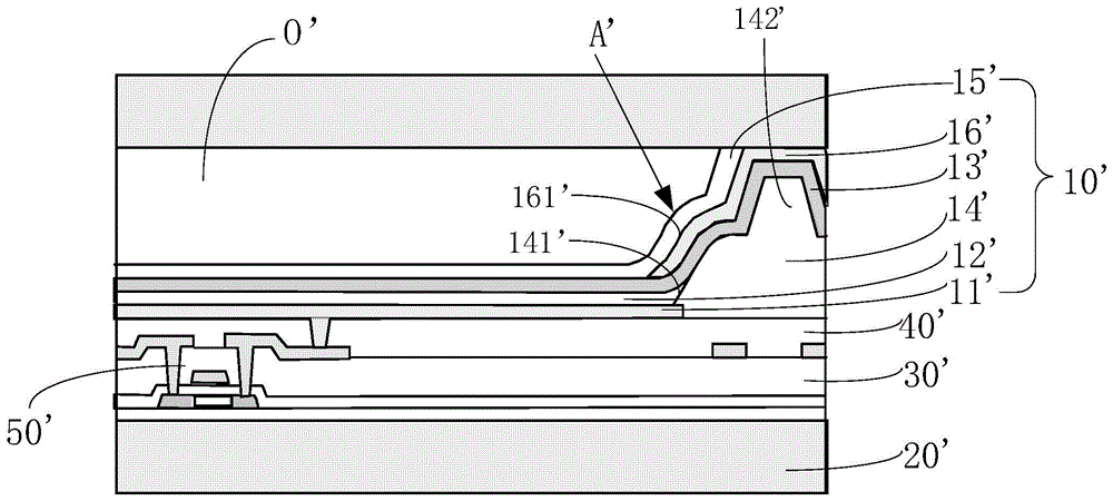
[0053] Unlike Example 1, as image 3 and Figure 4 As shown, in the inclined portion A', the reflective layer 16' covers the cathode layer 13', and the light extraction layer 15' is located on the reflective layer 16'.

[0054] like image 3 and Figure 4 As shown, over support portion 142', reflective layer 16' overlies cathode layer 13' and light extraction layer 15' overlies reflective layer 16'.

[0055] The reflective layer 16' is formed on the cathode layer 13' by physical vapor deposition (PVD) or chemical vapor deposition (CVD).

[0056] With the structure of Embodiment 2, in the inclined portion A', the reflective layer 16' directly covers the cathode layer 13', which can better reinforce the cathode layer 13' and prevent the cathode layer 13' from breaking; Compared with Embodiment 1, the structure of 2 can have a larger inclination angle, so as to have a higher light extraction efficiency.

[0057] Therefore, when the structure of Embodiment 2 is adopted, the i...


PUM


Abstract

The present invention relates to an organic light-emitting structure and an organic light-emitting device and a panel with the structure. In the organic light-emitting structure of the present invention, an inclined portion is formed on a pixel definition layer, and a reflective layer is provided in the inclined portion. The reflective layer has a relatively The inclined light reflecting surface of the organic light-emitting layer can improve the loss of light in the lateral direction, change the light output path in the lateral direction, and improve the light output efficiency; on the other hand, the reflective layer is located above the second electrode layer, which can prevent The fracture phenomenon that may occur in the second electrode layer due to the formation of an inclined structure.

Description

technical field [0001] The present invention relates to the field of organic electroluminescence, in particular to an organic light-emitting structure, an organic light-emitting device and an organic light-emitting panel having the structure. Background technique [0002] Organic light-emitting devices are devices that use the carriers injected after an applied voltage to recombine and excite organic materials to emit light. It has many advantages such as self-luminescence, high efficiency, low voltage, fast response, wide viewing angle, and can be used on flexible substrates. It can be made into a display. Or lighting devices, much attention from the society. [0003] Organic Light Emitting Diodes (OLEDs) are self-luminous display devices that are widely used in display and lighting fields. In order to ensure high functional reliability and low energy consumption of OLED devices, it is necessary to improve the External quantum efficiency of semiconductor light-emitting ele...

Claims


Application Information

Patent Timeline
Patent Type & Authority Applications(China)
IPC IPC(8): H01L51/52H01L27/32
Inventor 张其国陈志宏邹忠哲黄初旺
Owner EVERDISPLAY OPTRONICS (SHANGHAI) CO LTD
Why Eureka
Try Eureka