Grinding device for cement production

A grinding and cement technology, applied in grain processing, etc., can solve the problems affecting the use effect of cement, uneven powder size, low production efficiency, etc., achieve good particle size uniformity, improve use effect, hardness and durability Improved effect

Inactive Publication Date: 2016-10-26
无锡得戟重工有限公司
View PDF7 Cites 5 Cited by
  • Summary
  • Abstract
  • Description
  • Claims
  • Application Information

AI Technical Summary

Problems solved by technology

At present, there are two types of cement production processes in general manufacturers in the market, namely dry cement production process and wet cement production process. No matter what kind of cement production process is used, the grinding equipment is very critical, but the existing Most of the grinding equipment has low production efficiency, and the size of the final powder is uneven, and there are many impurities in it, which seriously affects the use effect of the final cement.

Method used


Image

  • Grinding device for cement production

Examples


Embodiment 1

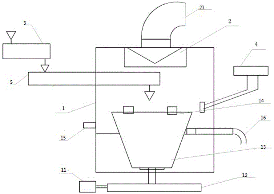
[0013] Such as figure 1 As shown, the present invention provides a grinding device for cement production, including a pulverizer body 1, the bottom end of the pulverizer body 1 is provided with a grinding disc 13 with an upward opening, and the grinding disc 13 is connected to a decelerating machine located outside the pulverizer body 1. machine 12, the reducer 12 is connected to the motor 11, a feeder 3 is arranged on one side of the pulverizer body 1, and a dryer 5 for receiving materials in the feeder 3 is arranged below the feeder 3, so The dryer 5 extends into the pulverizer body 1 and is located above the grinding disc 13. The dryer 5 is used to send materials to the grinding disc 13. The top of the pulverizer body 1 is located directly above the grinding disc 13 and is equipped with an intelligent powder selection device. Machine 2, the intelligent powder separator 2 is provided with a fine powder outlet 21, one side of the pulverizer body 1 is provided with an air inle...

Embodiment 2

[0015] Such as figure 1 As shown, the material is first placed in the feeder 3 and falls into the grinding disc 13 after being dried by the dryer 5. The material moves from the middle to the periphery under the action of the centrifugal force generated by the rotation of the grinding disc 13. The 13 raceways are fully pulverized by extrusion and grinding, and the electrical control system 4 is started, which sprays air into the grinding disc 13, and the air enters the grinding disc 13 and rotates up, bringing the pulverized materials to the grinding disc 13. Go to the upper powder separator 2 for powder selection, the coarse particles fall naturally, and at the same time mix with the newly added materials, and then enter the grinding table 13 again, and the fine particle clinker passes through the powder separator 2 from the fine powder outlet 21 After passing through a stainless steel filter screen, it is discharged.


PUM


Abstract

The invention discloses a grinding device for cement production. The grinding device comprises a smashing machine body; an abrasive disk is arranged at the bottom end in the smashing machine body, an upward opening is formed in the abrasive disk, and the abrasive disk is connected with a speed reducer which is arranged outside the smashing machine body; the speed reducer is connected with a motor, and a feeder is arranged on one side of the smashing machine body; a dryer for receiving materials in the feeder is arranged under the feeder, and the dryer stretches into the smashing machine body, is located above the abrasive disk, and is used for sending the materials into the abrasive disk; an intelligent powder choosing machine is arranged at the top end in the smashing machine body and right above the abrasive disk, and a fine powder outlet is formed in the intelligent power choosing machine. The grinding machine can enable larger particles in powder to continuously fall back into the abrasive disk to be smashed continuously, so that the final discharged cement powder has excellent fineness and is very good in particle uniformity. Thus, a cement using effect is remarkably improved, and the project quality of building engineering is guaranteed.

Description

technical field [0001] The invention specifically relates to a grinding device for cement production. Background technique [0002] Cement is a special material for the construction industry, and it is also a gelling material. It is an anhydrous solid substance that is generally in a destabilized state in the atmospheric environment. It can generally be dissolved in a reconciled aqueous solution and react in situ to release heat and form a gel. Congealing hydrates. Cementitious materials generally need to be fully ground to achieve their best efficacy in production and use. At present, there are two types of cement production processes in general manufacturers in the market, namely dry cement production process and wet cement production process. No matter what kind of cement production process is used, the grinding equipment is very critical, but the existing Most of the grinding equipment has low production efficiency, and the final powder size is uneven, and there are ma...

Claims


Application Information

Patent Timeline
Patent Type & Authority Applications(China)
IPC IPC(8): B02C15/00B02C23/24B02C23/12B02C23/14B02C23/16
CPCB02C15/00B02C23/12B02C23/14B02C23/16B02C23/24B02C2015/002
Inventor 丁亚平吴正初
Owner 无锡得戟重工有限公司
Why Eureka
Try Eureka