
Method and device for cutting metallic workpieces from a plate-shaped material

A plate-shaped, workpiece technology used in the field of cutting metal workpieces and devices composed of plate-shaped materials

Active Publication Date: 2016-10-26
TRUMPF WERKZEUGMASCHINEN GMBH & CO KG
View PDF6 Cites 4 Cited by
  • Summary
  • Abstract
  • Description
  • Claims
  • Application Information

AI Technical Summary

Problems solved by technology

The disadvantage of these methods is that they leave visible marks on the cut edges, at least when the microjoints or microwelds are mechanically separated

Method used


Image

  • Method and device for cutting metallic workpieces from a plate-shaped material
  • Method and device for cutting metallic workpieces from a plate-shaped material
  • Method and device for cutting metallic workpieces from a plate-shaped material

Examples


Embodiment Construction

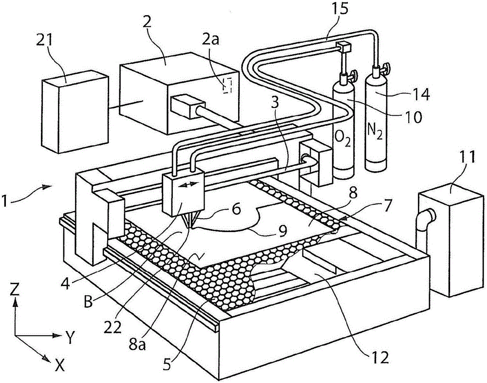
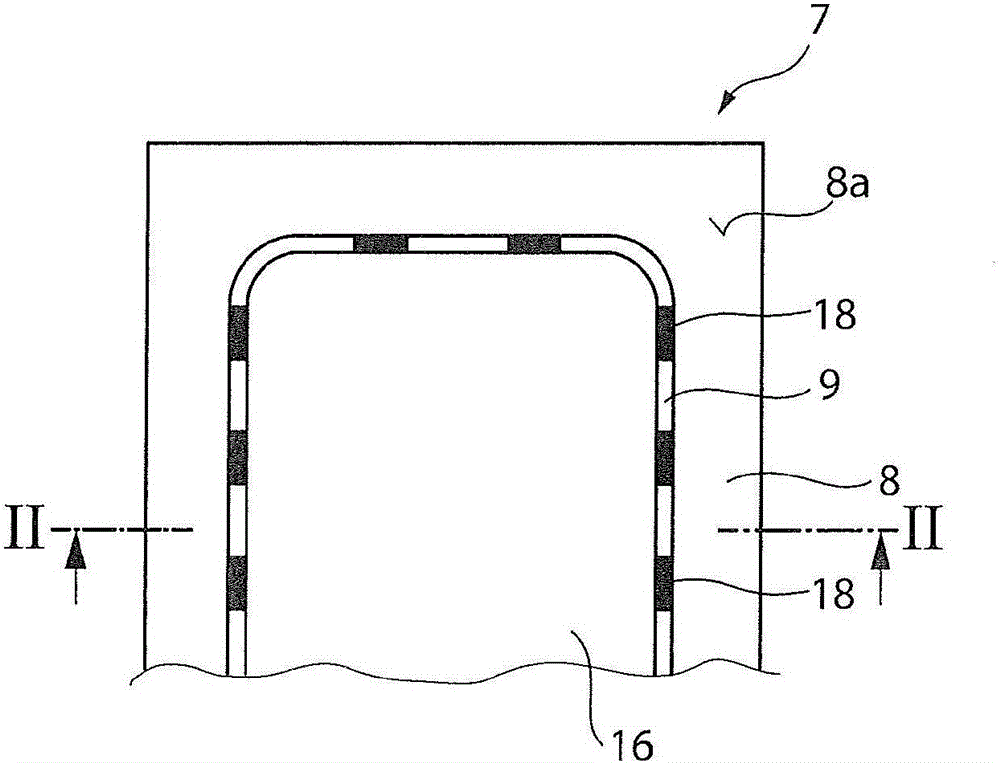
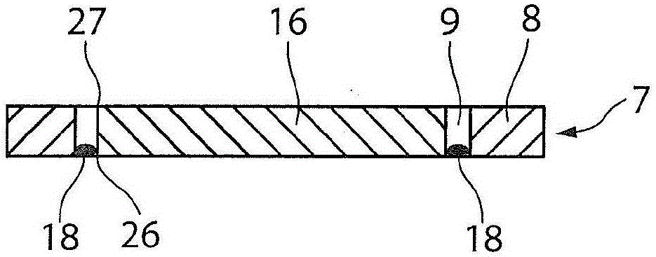
[0020] figure 1 CO for laser combustion cutting is shown as an example of a laser cutting machine 1 2 Laser cutter, the CO 2 Laser cutting machine has CO 2 Laser source, processing head 4 and workpiece support 5. The laser beam 6 generated by the laser source 2 or the resonator present in the laser source 2 is guided by means of the beam guiding device 3 from a deflecting mirror (not shown) to the processing head 4 and focused in the processing head and by means of the beam guide 3 . Yu Zai figure 1 The mirrors, also not shown in the figure, are oriented perpendicular to the surface 8 a of the plate-like material 7 . The beam axis (optical axis) of the laser beam 6 extends perpendicular to the surface 8 a of the plate-like material 7 . The laser beam acts on the sheet material 7 at the process point B together with the oxygen process gas jet 22 . Alternatively, the laser cutting machine 1 can have a solid-state laser as laser source, the radiation of which is guided to t...


PUM


Abstract

The invention relates to a method for cutting metallic workpieces (16) from a plate-shaped material (7) in a laser flame cutting process, in which a laser beam (6) with an oxygen process gas jet (22) passes through a cutting nozzle (20) 4) is directed at a processing location (B) on the plate-shaped material (7), wherein the laser beam (6) is moved with the process gas jet (22) across the plate-shaped material (7), so that a continuous cutting gap (9) (14) which deviates from the process gas (10) is fed to the processing location (B) during the cutting process, and the workpiece (16) is cut out of the plate - shaped material (7) to form a residual lattice (8) (Slag) is formed during the duration of the supply of the foreign gas in the cutting gap (9), which slag remains in the cutting gap (9) and partially closes the latter, so that the cut workpiece (16) is held in the residual lattice (8). The invention also relates to a laser cutting machine suitable for carrying out the method.

Description

technical field [0001] The invention relates to a method for cutting metal workpieces made of sheet-like material in a laser combustion cutting process, in which a laser beam with an oxygen process gas jet is directed at the workpiece through a cutting nozzle on a machining head of a laser cutting machine The laser beam with the oxygen process gas jet is moved on the workpiece, so that a continuous cutting gap is formed and the workpiece is cut out of the sheet material with the formation of the remaining grid. . The invention also relates to a laser cutting machine suitable for implementing the method. Background technique [0002] In the context of the present application, a plate-shaped material is also to be understood as a three-dimensional shaped material having an extension that is greater than the width. When laser-cutting a plate-shaped material, the cut parts may be insufficient due to their geometric shape or due to insufficient support of the workpiece support. ...

Claims


Application Information

Patent Timeline
IPC IPC(8): B23K26/38B23K26/14
CPCB23K26/14B23K26/38B23K2101/18B23K37/0235B23K26/0853B23K26/147B23K26/1476
Inventor T·凯泽
Owner TRUMPF WERKZEUGMASCHINEN GMBH & CO KG
Learn More