Automatic hole making device of robot and machining method

An automatic and robotic technology, applied in manufacturing tools, other manufacturing equipment/tools, manipulators, etc., can solve problems such as inability to realize automatic positioning, large system volume and weight, lack of hole position detection and normal alignment units, etc. , to achieve the effects of simple structure, simplified device structure and good developability

Active Publication Date: 2016-10-26
DALIAN UNIV OF TECH
View PDF8 Cites 15 Cited by
  • Summary
  • Abstract
  • Description
  • Claims
  • Application Information

AI Technical Summary

Problems solved by technology

This invention requires a specially designed CNC turntable, and the system has a large volume and weight; at the same time, th

Method used


Image

  • Automatic hole making device of robot and machining method
  • Automatic hole making device of robot and machining method
  • Automatic hole making device of robot and machining method

Examples


Embodiment 1

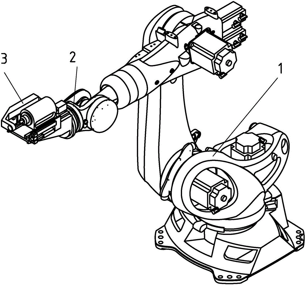
[0046] like Figure 1-Figure 7 As shown, a robot automatic hole-making device includes a six-axis serial robot arm 1, a mechanical arm end rotation mechanism 2 and an automatic hole-making end effector 3, and the six-axis serial robot arm 1 passes through the robot arm end rotation mechanism 2 is connected with the automatic hole making end effector 3,

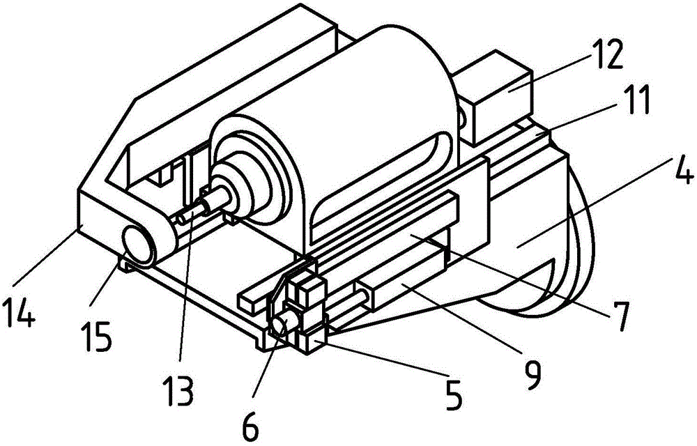
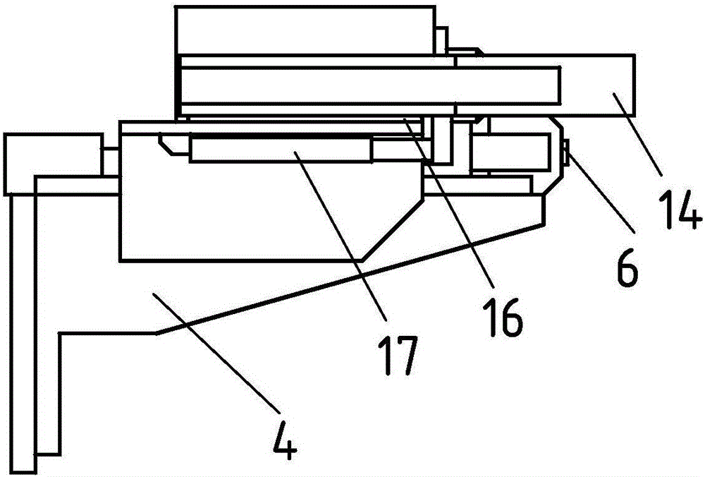
[0047] The automatic hole-making end effector 3 includes an automatic positioning and alignment module, a hole-making module, a pressure foot module and a frame 4,

[0048] The automatic positioning and correcting module includes four laser displacement sensors 5 that are centrally symmetrical and a CCD camera 6 located on the symmetrical center of the four laser displacement sensors 5, and the automatic positioning and correcting module is connected with the linear guide rail I7 The frame 4 is connected, the linear guide rail I7 is parallel to the rotation axis 8 of the rotating mechanism at the end of the mechanical arm, an...

Embodiment 2

[0059] like Figure 8-Figure 15 As shown, a robot automatic hole-making device includes a six-axis serial robot arm 1`, a mechanical arm end rotation mechanism 2` and an automatic hole-making end effector 3`, and the six-axis serial robot arm 1` passes through the mechanical The arm end rotation mechanism 2` is connected with the automatic hole-making end effector 3`,

[0060] The automatic hole making end effector 3` includes an automatic positioning and alignment module, a hole making module, a pressure foot module and a frame 4`,

[0061] The automatic positioning and correcting module includes four laser displacement sensors 5' that are centrally symmetrical and a CCD camera 6' located on the symmetrical center of the four laser displacement sensors 5', and the automatic positioning and correcting module passes through the linear guide rail I7' is connected to the frame 4', the linear guide rail I7' is parallel to the rotation axis 8' of the end rotation mechanism of the ...


PUM


Abstract

The invention discloses an automatic hole making device of a robot and a machining method. The hole making device comprises a six-shaft series-connection mechanical arm, a mechanical arm tail end rotating mechanism and an automatic hole making tail end executor; the six-shaft series-connection mechanical arm is connected with the automatic hole making tail end executor through the mechanical arm tail end rotating mechanism; and the automatic hole making tail end executor comprises an automatic positioning alignment module, a hole making module, a pressure foot module and a rack. The automatic hole making device of the robot has an automatic positioning alignment function, is high in hole making positioning precision, can achieve automatic hole making in cooperation with a mechanical arm and is high in machining efficiency. According to the automatic hole making device of the robot, conversion of different stations is achieved through the rotating freedom degree of the mechanical arm tail end rotating mechanism, and the device structure is simplified. The automatic hole making device of the robot can be additionally provided with other functional modules, is good in development performance, can integrate functional modules for riveting, hole making precision and quality detection and the like, adapts to different requirements and achieves various functions.

Description

technical field [0001] The invention belongs to the technical field of automatic hole-making of large aerospace components, and in particular relates to an automatic hole-making end effector installed with a six-degree-of-freedom manipulator as a carrier, which is used for automatic hole-making of aircraft wing or fuselage frame structural parts. A robot automatic hole-making device and a processing method for holes are disclosed. Background technique [0002] At present, most of the connection methods used in aerospace structural parts are mechanical connections, such as rivet connections or bolt connections, which require a large number of connection holes to be processed on the components. For example, there are thousands of riveting holes to be processed in the instrument compartment or finishing compartment of a large launch vehicle, more than 14,000 connection holes on each wing of an F-22 fighter jet, and more than 300 holes in a Boeing 747 aircraft. Thousands of con...

Claims


Application Information

Patent Timeline
IPC IPC(8): B25J11/00B23P23/04B25J19/02
CPCB23P23/04B25J11/005B25J19/023
Inventor 康仁科董志刚杨国林朱祥龙张园
Owner DALIAN UNIV OF TECH
Why Eureka
Try Eureka