3D curve-shaped propeller blades

A propeller, curved technology, applied in the directions of propellers, rotating propellers, rotary propellers, etc., can solve the problems of narrow application surface, limited thrust, blade damage, etc., and achieve low noise pollution, large propulsion, easy to spin Slow down effect

Inactive Publication Date: 2016-10-26
陈笠
View PDF0 Cites 2 Cited by
  • Summary
  • Abstract
  • Description
  • Claims
  • Application Information

AI Technical Summary

Problems solved by technology

[0004] In order to overcome the narrow application area of ​​the single design of the propeller, the high-speed rotating blades are easy to cause or be damaged by the outside world, and the thrust is still limited, but the ducted propeller equipment is bulky and heavy. The blade of the present invention adopts a 3D curved surface The helical structure forms a curved disk surface after rotating the propeller. Using the edge-to-edge cutting of the blade and radially pressing down the fluid on the spiral blade surface, a large area of ​​suction is generated on the curved disk surface, and the high pressure is formed in the body cavity of the curved disk surface, thereby generating Large jet propulsion

Method used


Image

  • 3D curve-shaped propeller blades
  • 3D curve-shaped propeller blades
  • 3D curve-shaped propeller blades

Examples


Embodiment 1

[0028] The existing propeller blade design has low efficiency in application, resulting in high energy consumption, short battery life, high-speed rotating blade tips are easily damaged, and are easy to harm the outside world, and the noise is relatively high.

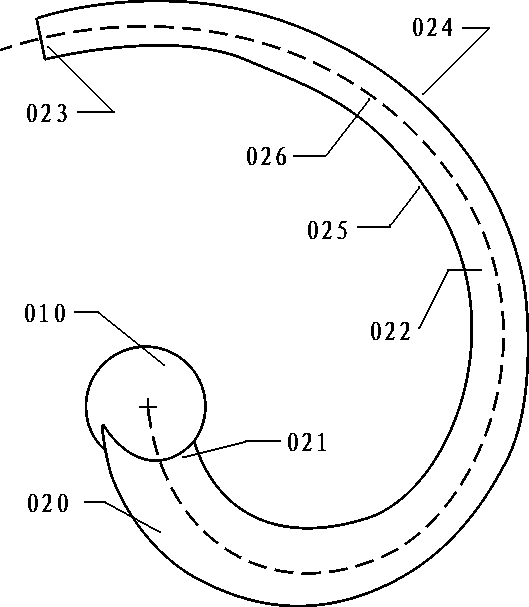
[0029] Based on this, the present invention proposes a novel propeller blade design scheme, figure 1 As shown, the diameter of the hub is designed to be 2.2cm, the radial curve 026 of the blade is designed as a 1 / 8 arc segment + Archimedes spiral, and the orthographic projection radius from the center of the hub to the outer edge of the blade tip is 10cm;

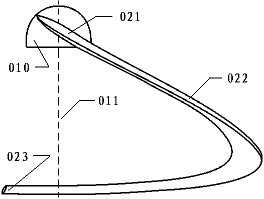
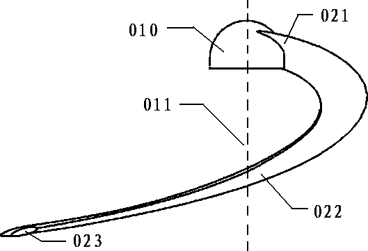
[0030] figure 2 As shown, the vertical height of the lateral projection from the blade root 021 to the blade tip 023 is designed to be 10cm, and the shape of the cut surface of the leaf is uniformly designed to be fusiform, with a thickness of 3mm;

[0031] blade root, figure 2 -021 has a blade width of 1.8cm, and its angle of attack is 20 degrees. The angle of ...

Embodiment 2

[0037] Such as Image 6 Shown is a schematic diagram of a complete propeller structure in Embodiment 2 of the present invention, such as Figure 5 As shown, the propeller is composed of a hub 010 and a blade 020 designed in Embodiment 1, and the two blades are symmetrical along the axis of the hub. When the paddle rotates around the center of the paddle hub, different parts of the paddle generate cutting and downward pressure against the fluid, forming a pressure difference so that a large amount of fluid enters from the curved disk surface and gathers in the body cavity of the disk surface. However, the fluid outflow surface is only the projected area The size of the propeller forms a channel effect, generates a certain high pressure, and ejects the inhaled fluid at a high speed, thereby generating a greater thrust, so that the equipment using the propeller can extend the endurance time and travel distance, and has higher performance.

[0038] It should be noted that the num...


PUM


Abstract

The blade shape of a propeller blade is characterized in that the blade is designed as a narrow and long blade, and the radial direction is curved in three-dimensional space. The main purpose is to provide efficient propulsion for light or other special aircraft, diving equipment, and ground maneuvering equipment after they are combined into propellers. The propeller itself has a certain duct fluid compression effect, which can increase the thrust under the same power drive; the design of the blade can reduce the damage caused by the blade tip to the outside world under high-speed rotation, and can protect the blade itself. At the same time, it operates at high speed in fluid media of different densities, and the transition dynamic performance is good. The invention is a propeller blade with ingenious design, wide application and superior performance.

Description

technical field [0001] The invention relates to a propulsion device in a fluid, especially capable of providing high-efficiency propulsion for light or other special aircraft, diving equipment, and ground maneuvering equipment. Background technique [0002] At present, the traditional propeller is to use the propulsion generated by the cutting of the blade relative to the fluid when the blade rotates. For different applications in different fluids, propellers are also specially designed for different purposes; and today’s propeller blades are basically designed to be radial (or fan-shaped propellers, although the length-to-width ratio of the blade is small, but still radial), the blade tip rotates at high speed It is easy to cause damage to the outside world or the blade itself due to external influences; the current technology, the wind-receiving surface of the isolated propeller is flat and circular, and it is difficult to form a duct effect. Even if the angle of attack is...

Claims


Application Information

Patent Timeline
Patent Type & Authority Applications(China)
IPC IPC(8): B63H1/26B64C11/20B64C11/18
CPCB63H1/26B64C11/18B64C11/20
Inventor 陈立
Owner 陈笠
Why Eureka
Try Eureka