Bionic tail fin capable of being used for overwater measuring equipment power

A technology for measuring equipment and tail fins, applied in the field of bionic tail fins, can solve the problems of increasing the weight of ships or submarines, increasing equipment investment, and large friction, and achieving the effects of low labor maintenance costs, improved propulsion efficiency, and improved energy-saving effects.

Inactive Publication Date: 2016-10-26
HENAN UNIVERSITY
View PDF9 Cites 5 Cited by
  • Summary
  • Abstract
  • Description
  • Claims
  • Application Information

AI Technical Summary

Problems solved by technology

At present, the driving method of this simple artificial caudal fin is divided into the following two methods: one is to use stepper motor or servo motor to drive, the mechanism of this driving method is complicated and the cost is higher; the other is to use crank-link mechanism mechanical Device drive, this drive method is to convert circular motion into reciprocating motion, because it is mainly composed of mechanical components, so the friction is large, the wear is also large, and the efficiency is low
[0005] In addition, a superconducting magnetic fluid thruster is also used. Although the superconducting electromagnetic fluid thruster has the characteristics of quietness, no noise, and easy operation, the cost of the superconducting electromagnetic fluid thruster is high, and the speed is slow. A large generator is needed as power, which will not only increase the weight of the ship or submarine, but also the speed of the power system of the large generator as the driving force is higher than that of the superconducting magnetic fluid propeller, which cannot directly drive the superconducting magnetic fluid propeller, and needs to be increased Equipment investment will make the cost higher

Method used


Image

  • Bionic tail fin capable of being used for overwater measuring equipment power
  • Bionic tail fin capable of being used for overwater measuring equipment power
  • Bionic tail fin capable of being used for overwater measuring equipment power

Examples


Embodiment Construction

[0017] The specific embodiments of the present invention will be described in detail below with reference to the accompanying drawings.

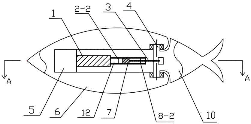
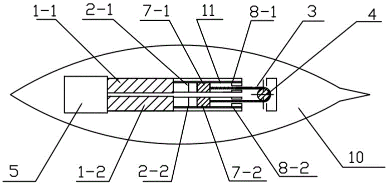
[0018] Figure 1 to Figure 2 Among them, the tail fin shell is formed by the fish tail 10 through the sprocket drive shaft 4 integrally connected with the fish body 6 and the fish tail 10 can swing left and right under the action of the sprocket drive shaft 4. The sprocket drive shaft 4 is connected to the slider 7-1 and the slider 7-2 located in the fish body 6 through the two ends of the chain 3 connected with the chain drive, respectively, at the two ends of the slider 7-1 and the slider 7-2 Set light-shielding plates (not shown in the figure) respectively, the light-shielding plates are parallel to the horizontal plane and perpendicular to the corresponding sliders 7-1 and 7-2, and are pasted on the light-shielding plates with a certain thickness and have a protective function Sponge pad. The slider 7-1 and the slider 7-2 are respectively...


PUM


Abstract

The invention provides a bionic tail fin capable of being used for overwater measuring equipment power. The bionic tail fin is mainly characterized in that transmission shafts in transmission connection with two sliding blocks connected to two guide rails are arranged in a tail fin shell, sliding block movement starting and stopping limiting pieces are arranged at the position, at the two ends of each sliding block, of each guide rail, photocoupling switch devices are arranged at the positions of the sliding block movement starting and stopping limiting pieces of each sliding block, the two ends of each sliding block are provided with light shading boards, one end of each guide rail is provided with an electromagnet, and the electromagnets are connected with an electric controller. The bionic tail fin has the beneficial effects of being environment-friendly, free of pollution, good in silencing effect, simple in structure, low in cost and long in service life, and the propelling efficiency and the energy-saving effect can be effectively improved. The bionic tail fin can be used for a system such as a small hydrographic survey vessel with the relatively high self-restraint time requirement, can also be used as a propelling system for a pure electric propelling ship and further can be used for certain special occasions, such as underwater acoustical signal collection, with the special requirements for the noise of the propelling system.

Description

Technical field [0001] The invention relates to a power mechanism for driving water measuring equipment, in particular to a bionic tail fin which can be used for power of water measuring equipment, which is suitable for driving movement of water and water measuring equipment. Background technique [0002] Generally, there are many types of power mechanisms that drive objects in and above water, mainly propellers, mechanisms based on bionic principles such as artificial fins, superconducting magnetic fluid thrusters, etc. [0003] Although the propeller as a ship driving mechanism has been widely used in ship driving, its shortcomings such as low transmission efficiency, high energy consumption, and high noise are obvious. [0004] In recent years, many people have used the principle of bionics to make simple artificial tail fins based on fish tails, which are used as the power to drive the ship forward. It has high efficiency, low noise and energy saving, which is another new develop...

Claims


Application Information

Patent Timeline
Patent Type & Authority Applications(China)
IPC IPC(8): B63H1/36
CPCB63H1/36
Inventor 童海滨骆国强芦冠奇谢睿臻杨天骄
Owner HENAN UNIVERSITY
Why Eureka
Try Eureka