Double-sided centrifugal impeller and machining method thereof

A centrifugal impeller, double-sided technology, applied in the field of compressors, can solve the problems of inability to further process the center of the disk body, scrapped centrifugal impeller disks, and high stress on the disk center, and reduce the difficulty of processing technology, cooling stress, and cooling disk body deformation. Effect

Inactive Publication Date: 2016-10-26
CHINA AVIATION POWER MACHINE INST
View PDF6 Cites 4 Cited by
  • Summary
  • Abstract
  • Description
  • Claims
  • Application Information

AI Technical Summary

Problems solved by technology

[0003] The disadvantage of the existing double-sided intake centrifugal impeller disc is that due to the limitation of the processing of the left and right blades and the limitation of the processing tool, the impeller disc 103 can only be processed at the left inlet processing surface 104 and the right inlet processing surface 105. The center part cannot be further processed, resulting in too much stress on the center of the disc and cannot be released, resulting in large deformation, and at the same time, it is impossible to reduce weight. Due to the excessive weight of the wheel disc, it will cause serious rotor dynamics problems
In addition, since the disk body is a whole, when either the left blade or the right blade is partially damaged, the entire centrifugal impeller disk may be scrapped, resulting in greater losses

Method used


Image

  • Double-sided centrifugal impeller and machining method thereof
  • Double-sided centrifugal impeller and machining method thereof
  • Double-sided centrifugal impeller and machining method thereof

Examples


Embodiment 1

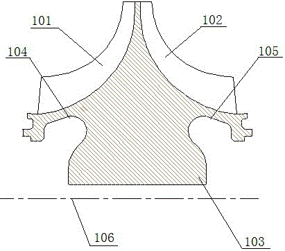
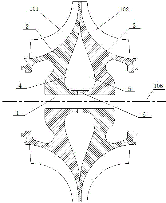
[0026] This embodiment provides a double-sided centrifugal impeller, such as figure 2 As shown, it includes an impeller disc 103, a left blade 101, a right blade 102 and an axis hole 1 passing through the impeller rotation axis 106, and the impeller disc 103 includes a left disc 2 and a right disc 3; the impeller disc 103 There is a cavity in the center; the impeller disc 103 is spliced ​​by two pieces, along the junction of the left disc 2 and the right disc 3, perpendicular to the axis of rotation 106, the impeller disc 103 is divided into There are two pieces, and a cavity is opened on the dividing surface of the two pieces. The cavity includes a left cavity 4 located at the left wheel 2 and a right cavity 5 located at the right wheel 3, and the size and shape of the left cavity 4 and the right cavity 5 are the same.

[0027] The cavity is annular, and the axis of the annular cavity is the rotation axis 106 of the impeller.

[0028] A ventilation slot 6 is provided on a ...

Embodiment 2

[0033] This embodiment provides a double-sided centrifugal impeller, such as figure 2 As shown, it includes an impeller disc 103, a left blade 101, a right blade 102 and an axis hole 1 passing through the impeller rotation axis 106, and the impeller disc 103 includes a left disc 2 and a right disc 3; the impeller disc 103 There is a cavity in the center; the impeller disc 103 is spliced ​​by two pieces, along the junction of the left disc 2 and the right disc 3, perpendicular to the axis of rotation 106, the impeller disc 103 is divided into There are two pieces, and a cavity is opened on the dividing surface of at least one piece. The cavity includes a left cavity 4 located at the left wheel 2 and a right cavity 5 located at the right wheel 3, and the size and shape of the left cavity 4 and the right cavity 5 are the same.

[0034] The cavity is annular, and the axis of the annular cavity is the rotation axis 106 of the impeller.

[0035] A ventilation slot 6 is provided o...

Embodiment 3

[0041]This embodiment provides a processing method for the double-sided centrifugal impeller described in Embodiment 1 and Embodiment 2, wherein the cavity and the ventilation groove are formed by die forging or machining.

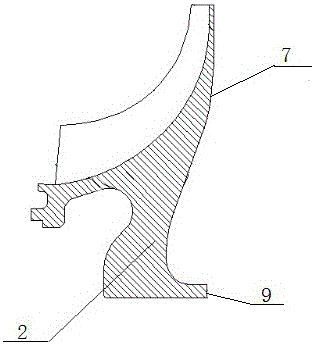
[0042] In this embodiment, the cavity is formed after processing the split surface, and the surface of the cavity is called the cavity processing surface; in this embodiment, the cavity processing surface 7, the cavity processing surface 2 8, the ventilation groove side 9, and the ventilation groove Edge 2 10 does not require high machining accuracy, and the profile can be directly forged in the blank state, thereby greatly reducing the processing cost. For the impeller disc described in this embodiment, both the left disc and the right disc can be die forged during mass production, thereby reducing the weight of the blank and reducing the cost. In small batch production, machine addition is preferred.


PUM


Abstract

The invention discloses a double-sided centrifugal impeller and a machining method thereof. The double-sided centrifugal impeller comprises an impeller disk, a left blade, a right blade and an axis hole penetrating through the rotation axis of the impeller, wherein the impeller disk comprises a left disk body and a right disk body; cavities are formed in the impeller disk; the impeller disk is formed by splicing at least two blocks; and the cavities are formed by excavating a part of material from the contact face of at least one block. The centrifugal impeller of a novel structure not only overcomes the defect that a center disk of a conventional centrifugal impeller cannot be machined, but also can achieve air convection in the center of the disk through vent grooves, the pressure of the center of the disk is automatically adjusted through centrifugal force on the air in the center of the disk and pressure generated by heat conduction expansion, and the cooling function and the function of reducing the disk deformation can be achieved. Meanwhile, when any block of the impeller disk is severely damaged, the damaged block can be replaced, so that the loss is reduced and cost is saved. The impeller disk is divided into the multiple blocks, then each block can be machined independently, and the machining process difficulty is reduced compared with that of double-sided overall machining.

Description

technical field [0001] The present invention relates to the technical field of compressors, and more specifically, to a double-sided centrifugal impeller. Background technique [0002] The structure of an existing double-sided intake centrifugal impeller is as attached figure 1 Shown; Centrifugal impeller is made of left blade 101, right blade 102 and impeller disc 103, and its axis of rotation is 106. When the centrifugal impeller is working, the airflow flows along with the inlets of the left blade 101 and the right blade 102 to rotate and pressurize. [0003] The disadvantage of the existing double-sided intake centrifugal impeller disc is that due to the limitation of the processing of the left and right blades and the limitation of the processing tool, the impeller disc 103 can only be processed at the left inlet processing surface 104 and the right inlet processing surface 105. The central part cannot be further processed, resulting in excessive stress on the center ...

Claims


Application Information

Patent Timeline
Patent Type & Authority Applications(China)
IPC IPC(8): F04D29/28
CPCF04D29/284F04D17/105F04D29/281
Inventor 黄生勤李维邹学奇邬国凡谢宁军查小晖
Owner CHINA AVIATION POWER MACHINE INST
Why Eureka
Try Eureka