Pipeline and pipeline system

A pipeline and main pipe technology, applied in the field of pollutant treatment, can solve the problems of limiting the extraction capacity of the extraction tube, the effect of gas injection is not obvious, and the injection tube extends in one direction, so as to facilitate installation and transportation, and improve extraction or injection Efficiency and extraction or injection capacity, effect of increasing extraction or injection area

Active Publication Date: 2016-10-26
BCEG ENVIRONMENTAL REMEDIATION CO LTD
View PDF6 Cites 6 Cited by
  • Summary
  • Abstract
  • Description
  • Claims
  • Application Information

AI Technical Summary

Problems solved by technology

[0005] The above-mentioned extraction tube still has the following defects in use: the body of the extraction tube extends along a single direction, and is limited by the working capacity of the air pump. After the extraction tube is vertically inserted into the soil, the load of the extraction tube The degree of pressure can only radiate to a certain range in the circumference of the extraction tube, that is, in the horizontal area far from the pores of the extraction tube, the extraction effect is not obvious, which limits the extraction capacity of the extraction tube
[0006] In addition, in the treatment of pollutants, it is often necessary to inject high-temperature gas into the soil through pipelines to heat volatile organic pollutants. The structure of the existing injection pipeline is similar to that of the above-mentioned extraction tube, and there is also Insufficient that it can only extend along a single direction, which leads to the fact that when the gas is injected, the injected gas can only radiate to the circumference of the injection pipe, and for the horizontal area far away from the pipe, the injection effect of the gas is not obvious, thus affecting The overall injection effect

Method used


Image

  • Pipeline and pipeline system

Examples


Embodiment 1

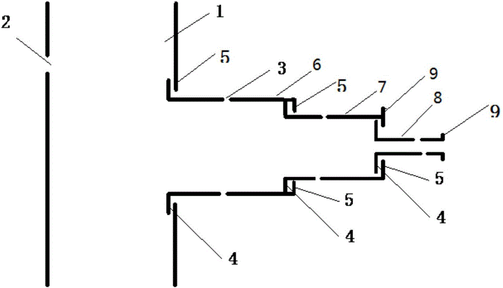
[0047] figure 1 The pipeline provided by this embodiment is shown, including a main pipe 1, a plurality of first air holes 2 are provided on the pipe body of the main pipe 1; and a branch pipe, the branch pipe communicates with the main pipe 1, and the axis of the branch pipe is connected to the The axes of the main pipes 1 form an included angle greater than 0 degrees and less than or equal to 90 degrees, and a plurality of second air holes 3 are arranged on the branch pipes.

[0048] By arranging a branch pipe which communicates with the main pipe 1 and has a number of second air holes 3 arranged at a certain angle, the effective extraction area of ​​the main pipe 1 is extended from the extension direction (vertical direction) of the main pipe 1 in the prior art. , extending to a horizontal direction perpendicular to the extension direction of the main pipe 1 or a direction inclined at a certain angle to the horizontal direction. When the pipeline is used for gas phase extra...

Embodiment 2

[0074] This embodiment provides a gas injection pipeline. The structure of the pipeline is the same as that described in Embodiment 1. In this embodiment, the pipeline is used for gas injection, and the injected gas passes through the main pipe and several nested connections in sequence. The circular tube makes the gas to be injected move in a direction perpendicular to the horizontal direction of the main pipe or inclined at a certain angle to the horizontal direction, and finally enters the underground soil through the second air hole on the composite casing. Therefore, the overall injection area of ​​the pipeline is effectively increased, and the injection efficiency of the gas is improved.

[0075] Specifically, the injected gas can be water vapor. When the high-temperature water vapor is injected into the ground, the volatile organic pollutants in the soil can be changed into a gas phase, and then the gas phase pollutants can be extracted to remove the pollutants. the goa...

Embodiment 3

[0078] This embodiment provides a pipeline system, including a pipeline, and a main pipe lifting device for raising or lowering the main pipe. Through the main pipe lifting device, the extraction pipeline or injection pipeline involved in embodiment 1 or embodiment 2 can be accurately parked at a specific position.

[0079] Specifically, the main pipe lifting device is connected to the pipeline. When extraction or gas injection operation is required, the injection pipeline or extraction pipeline involved in embodiment 1 or embodiment 2 is connected to the main pipe lifting device. Under the action, it extends down along the soil, and when it reaches a specific position, the distance monitoring device sends a signal to stop the main pipe from moving.


PUM


Abstract

The invention provides a pipeline. Through the arrangement of branch pipes which communicate with a main pipe and are arranged at certain angles and provided with a plurality of second air holes, the effective extraction or injection area of the main pipe is expanded in the horizontal direction perpendicular to the extending direction of the main pipe or in the direction inclined by a certain angle relative to the horizontal direction from the area around the pipe-diameter portion in the extending direction (the vertical direction) of the main pipe in the prior art, so that the overall extraction or injection area of the pipeline is effectively enlarged, and the gas extraction or injection capacity is improved.

Description

technical field [0001] The invention relates to the field of pollutant treatment, in particular to a pipeline, especially a pipeline with a relatively large extraction or injection range. Background technique [0002] With the process of industrialization, urbanization and modern agriculture in our country, soil pollution is becoming more and more serious. Especially heavy metal pollution and organic pollution are the most prominent. These pollutants have the characteristics of long persistence and high toxicity, often pollute surface water and groundwater, and may endanger human life and health through food chains and other channels. [0003] Soil gas phase extraction technology is the main method to remove organic pollutants at this stage. Firstly, heating technology is used to transform the volatile organic compounds in the soil from liquid phase to gas phase, and then the extraction tube is evacuated by vacuum technology to make the extraction A pressure or concentratio...

Claims


Application Information

Patent Timeline
Patent Type & Authority Applications(China)
IPC IPC(8): F16L27/12F17D1/02B09C1/06B09C1/00
CPCB09C1/005B09C1/06F16L27/12F17D1/02
Inventor 李书鹏孙尧刘阳李庆李季韦云霄
Owner BCEG ENVIRONMENTAL REMEDIATION CO LTD
Why Eureka
Try Eureka