
Distributed fiber vibration sensing system capable of eliminating declining noises and demodulation method of system

A technology of vibration sensing system and distributed optical fiber, applied in the direction of measuring ultrasonic/acoustic/infrasonic waves, measuring devices, instruments, etc. problem, to achieve the effect of high signal-to-noise ratio, large spatial resolution, and long detection distance

Active Publication Date: 2016-10-26
宁波联河光子技术有限公司
View PDF11 Cites 25 Cited by
  • Summary
  • Abstract
  • Description
  • Claims
  • Application Information

AI Technical Summary

Problems solved by technology

[0006] Aiming at the defects of low signal-to-noise ratio and inability to eliminate polarization fading and interference fading noise in the prior art, the present invention proposes a distributed optical fiber vibration sensing system and its demodulation method that can eliminate fading noise. The series signal performs vibration detection on the sensing fiber, the returned Rayleigh backscattered light beats the reference light, and then uses a matched filter to obtain phase information, and then uses the "frequency conversion-phase shift average" method to perform depolarization fading and interference fading , according to the phase information without fading noise to accurately locate the position of the vibration point and the vibration waveform, the signal-to-noise ratio is high

Method used


Image

  • Distributed fiber vibration sensing system capable of eliminating declining noises and demodulation method of system
  • Distributed fiber vibration sensing system capable of eliminating declining noises and demodulation method of system
  • Distributed fiber vibration sensing system capable of eliminating declining noises and demodulation method of system

Examples


Embodiment 1

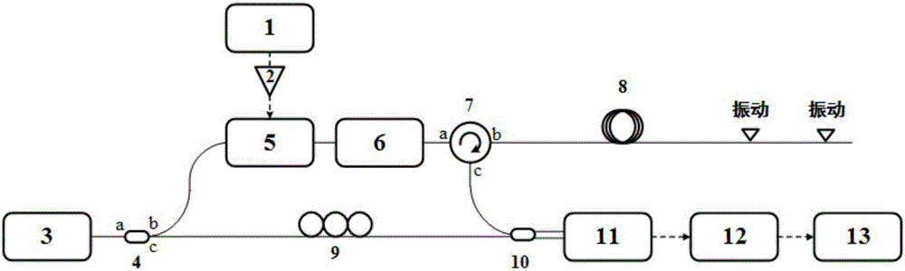
[0036] Such as figure 1As shown, this embodiment includes: a signal generation module, a narrow linewidth laser light source module, a frequency-sweeping pulse module, a circulator 7, a sensing fiber 8, a coherent receiving module, a photoelectric conversion module and a digital signal processing module, wherein: The signal generating module inputs the amplified frequency sweeping radio frequency pulse train signal to the frequency sweeping and cutting pulse module, and at the same time the signal generating module sends a trigger signal to the digital signal processing module; the ultra-narrow linewidth laser generated by the narrow linewidth laser light source module enters the a port branch There are two channels, one is the detection light input to the frequency sweeping pulse module through the b port, and the other is the reference light input to the coherent receiving module through the c port; The a port of the circulator 7 is input and output from the b port to the se...


PUM


Abstract

The invention relates to a distributed fiber vibration sensing system capable of eliminating declining noises and a demodulation method of the system. The system comprises a signal generation module, a narrow linewidth laser source module, a frequency-sweeping light chopping pulse module, a circulator, a sensing fiber, a coherent reception module, a photoelectric conversion module and a digital signal processing module; a computer generates multiple digital band pass filters of different frequency ranges but not overlapped and combines original data segments from multiple frequency-sweeping detection light pulses to obtain a reflectivity curve of the sensing fiber; phase-shaft averaging is carried out on the reflectivity curve to obtain multiple interference-free and polarization-declining integrated reflectivity curves; delay differential processing is carried out on the integrated reflectivity curves to obtain phase differential curves; variances of the phase differential curves are solved to obtain a phase variance curve; and a vibration point is determined according to variances in the phase variance curve, and position and vibration waveform of the vibration point are obtained. According to the system and method of the invention, design is reasonable, the positioning accuracy is high, and space resolution and long detection distance can be obtained at the same time.

Description

technical field [0001] The invention relates to a technology in the field of optical fiber sensing, in particular to a distributed optical fiber vibration sensing system capable of eliminating fading noise and a demodulation method thereof. Background technique [0002] Vibration sensing technology is widely used in engineering fields, such as boundary intrusion monitoring, structural health monitoring, oil pipeline safety monitoring, seismic wave monitoring, etc. Traditional vibration sensors are generally mechanical or electromagnetic, and there are many problems. For example, in a strong electric field environment, traditional vibration sensors are susceptible to electromagnetic interference and cannot work normally; in an inflammable and explosive environment, electric sparks will be generated. Causing accidents; In remote locations, there are power supply issues; Distributed sensing cannot be achieved. These defects severely limit the practical application of tradition...

Claims


Application Information

Patent Timeline
IPC IPC(8): G01H9/00
CPCG01H9/004
Inventor 何祖源刘庆文陈典樊昕昱
Owner 宁波联河光子技术有限公司
Learn More