Three-layer micro-bridge structure, three-layer uncooled micro-bolometer and preparation method thereof

A micro-bridge structure and micro-bridge technology, applied in the field of infrared detectors, can solve the problems of single-layer micro-bridge structure with only one resonant cavity, the influence of device thermal and electrical performance, and the lack of mechanical stability of S-shaped bridge legs. Improved absorption efficiency, easier device performance, and improved temperature rise

Inactive Publication Date: 2016-10-26
UNIV OF ELECTRONICS SCI & TECH OF CHINA
View PDF9 Cites 12 Cited by
  • Summary
  • Abstract
  • Description
  • Claims
  • Application Information

AI Technical Summary

Problems solved by technology

[0010] In the traditional single-layer L-shaped micro-bridge structure, the length of the bridge legs is not enough, which leads to poor heat insulation effect of the whole device. To increase the heat insulation effect of the device, the bridge legs must be increased, and the size of the pixel cannot be reduced, otherwise the device The thermal and electrical properties will be greatly affected, and because the single-layer micro-bridge structure has only one resonant cavity, there is still insufficient optical absorption; although the new S-type double-layer micro-bridge structure designed in the United States has two resonant cavities, The optical absorption effect of the device is better, but the mechanical stability of the S-shaped bridge legs is not as good as the single-layer L-shaped structure

Method used


Image

  • Three-layer micro-bridge structure, three-layer uncooled micro-bolometer and preparation method thereof
  • Three-layer micro-bridge structure, three-layer uncooled micro-bolometer and preparation method thereof
  • Three-layer micro-bridge structure, three-layer uncooled micro-bolometer and preparation method thereof

Examples


Embodiment Construction

[0046] Embodiments of the present invention are described below through specific examples, and those skilled in the art can easily understand other advantages and effects of the present invention from the content disclosed in this specification. The present invention can also be implemented or applied through other different specific implementation modes, and various modifications or changes can be made to the details in this specification based on different viewpoints and applications without departing from the spirit of the present invention.

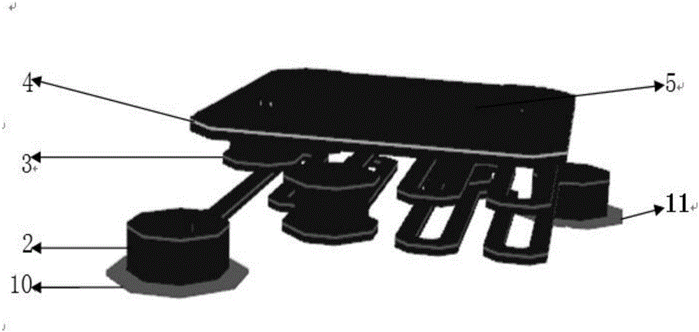
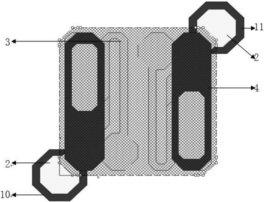
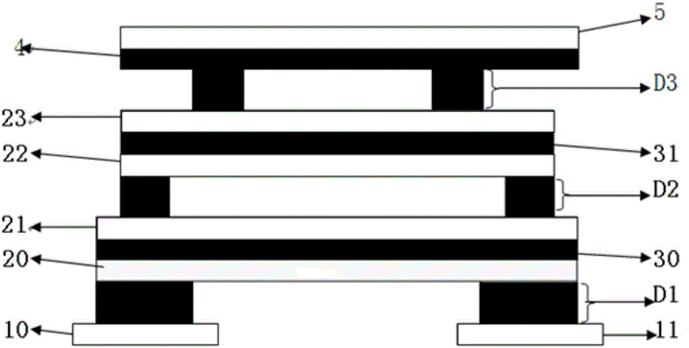
[0047] A three-layer microbridge structure, including a bridge deck, a second layer of microbridges, a first layer of microbridges, left and right aluminum electrodes embedded between silicon substrates, between the bridge deck and the second layer of microbridges, the first Isolation layers are provided between the micro-bridge on the second floor and the micro-bridge on the first layer, and between the micro-bridge on the first layer...


PUM


Abstract

A three-layer micro-bridge structure provided by the present invention comprises a bridge surface, a second-layer micro bridge, a first-layer micro bridge and left and right aluminum electrodes, and a light absorption material, a thermistor thin film and a passivation layer are laid on the uppermost bridge surface of the micro-bridge structure. An upper-layer optical resonant cavity is formed between the bridge surface and the second-layer micro bridge, an intermediate-layer optical resonant cavity is formed between the two layers of micro bridge, and a lower-layer optical resonant cavity is formed between the first-layer micro bridge and a bottom-layer silicon substrate. The present invention also provides a three-layer uncooled micro-bolometer containing the micro-bridge structure and a preparation method of the three-layer uncooled micro-bolometer. The micro-bridge structure of the present invention has three resonant cavities, so that the optical absorption efficiency is improved greatly. Secondly, during a simulation process, on a same stress condition, the deformation amount of a three-layer S-shaped micro-bridge structure is smaller than the deformation amounts of a single-layer S-shaped micro-bridge structure and a double-layer S-shaped micro-bridge structure, thereby guaranteeing the good mechanical stability of the micro-bridge structure. Meanwhile, the increase in the lengths of the bridge legs also enables the overall temperature rise of a device to be improved.

Description

technical field [0001] The invention relates to the field of infrared detectors, in particular to a three-layer microbridge structure, a three-layer uncooled microbolometer comprising the microbridge structure and a preparation method thereof. Background technique [0002] Infrared radiation has a wide range of applications, including communications, medical treatment, chemistry, biology, warfare and many other fields. According to the different wavelength ranges of infrared radiation, corresponding to different sources, propagation paths and detectors, the entire infrared spectral region can be divided into four bands according to the band size, which are: near infrared (NIR: 0.75 ~ 3μm), Chinese and foreign Red (MIR: 3-6μm), far-infrared (FIR: 6-15μm) and extreme far-infrared (15-1000μm). And in the atmosphere, the mid-infrared band and the long-wave infrared band have two atmospheric windows of 3-5 μm and 8-14 μm; infrared light is invisible light, and we can convert inv...

Claims


Application Information

Patent Timeline
Patent Type & Authority Applications(China)
IPC IPC(8): G01J5/20
CPCG01J5/023G01J5/024G01J5/20
Inventor 陈超王涛马振东马家锋伍浏权齐元
Owner UNIV OF ELECTRONICS SCI & TECH OF CHINA
Why Eureka
Try Eureka