C-type-sleeve all-dielectric self-supporting optical cable used for access network and manufacturing method thereof

A self-supporting optical cable and access network technology, applied in the direction of light guide, optics, optical components, etc., can solve the problems affecting communication and high cost of optical cables, achieve stable signal transmission, low price, and reduce manufacturing costs and construction costs.

Active Publication Date: 2016-10-26
JIANGSU HENGTONG PHOTOELECTRIC
View PDF7 Cites 0 Cited by
  • Summary
  • Abstract
  • Description
  • Claims
  • Application Information

AI Technical Summary

Problems solved by technology

Traditional self-supporting aerial optical cables will be damaged by mechanical factors or environmental factors, the cost of repairing or re-laying optical cables is high, and it will affect communication

Method used


Image

  • C-type-sleeve all-dielectric self-supporting optical cable used for access network and manufacturing method thereof
  • C-type-sleeve all-dielectric self-supporting optical cable used for access network and manufacturing method thereof
  • C-type-sleeve all-dielectric self-supporting optical cable used for access network and manufacturing method thereof

Examples


Embodiment 1

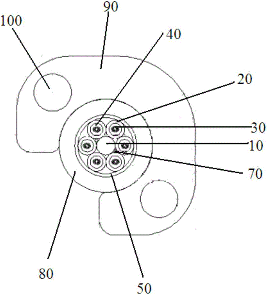
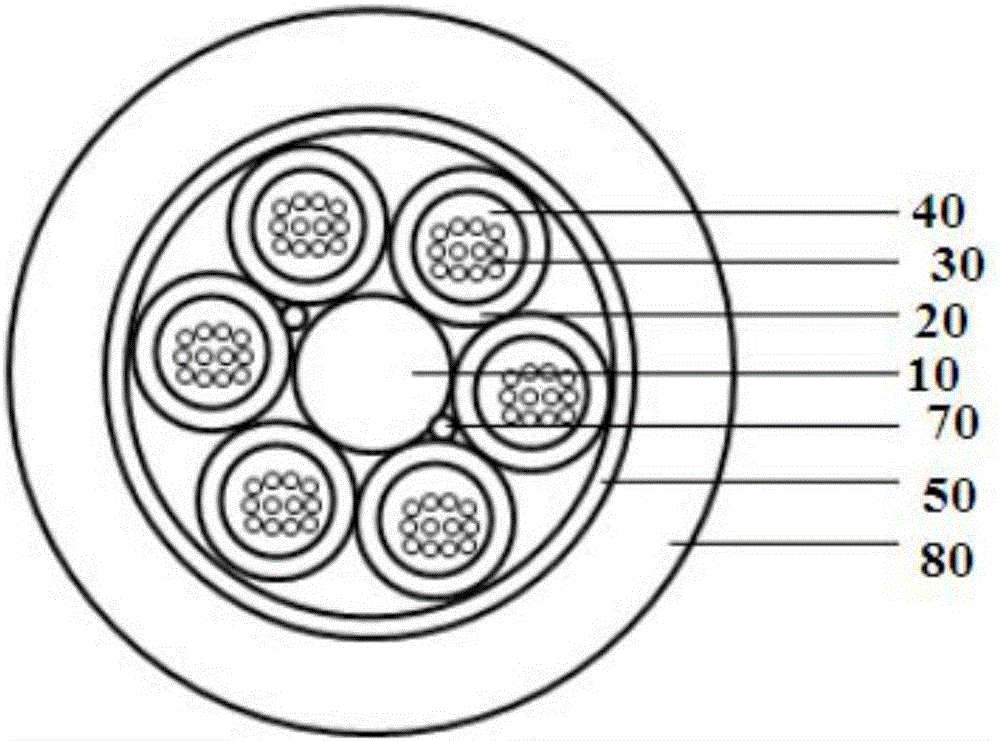
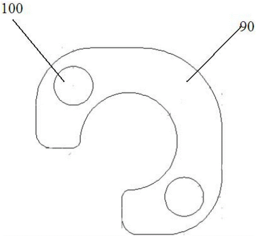
[0034] refer to Figure 1-3 As shown, this embodiment discloses a C-type sleeve full-dielectric self-supporting optical fiber cable for access networks. Its structure is divided into two parts, mainly including: an optical unit part and a load-bearing component part. The above-mentioned optical unit part includes: A central reinforcement 10 arranged in the center, a plurality of loose tubes 20 are arranged on the outer periphery of the central reinforcement 10, and a plurality of optical fibers 30 are arranged in each of the above-mentioned loose tubes 20, and each of the above-mentioned loose tubes 20 is filled with fiber paste 40 , or the inside of the loose tube 20 is dry, using water-blocking powder or water-blocking yarn as the water-blocking material, the loose tube 20 and the optical fiber 30 form a cable core, and the filling method of the cable core is dry filling, and the dry filling includes: A water-blocking yarn 70 is provided inside the central reinforcement 10 a...

Embodiment 2

[0042] The structure of the optical cable in Example 2 is the same as that in Example 1, and the formulation of the above-mentioned HDPE resin protective sheath material is shown in Table 2.

[0043] C type protective cover HDPE material formula table in the embodiment 2 of table 2

[0044] composition

Embodiment 3

[0046] The structure of the optical cable in Example 3 is the same as in Example 1, and the formulation of the HDPE resin protective sheath material is shown in Table 3.

[0047] C-type protective cover HDPE material formula table in the embodiment 3 of table 3

[0048] composition

Content (parts by weight)

HDPE resin

100

glass fiber

10

flame retardant

45

lubricant

13

antioxidant

0.5

UV absorber

3

filler

15

colorant

1

[0049] In the above-mentioned embodiments 1-3, the above-mentioned flame retardant includes: aluminum hydroxide, melamine cyanurate, and polyspirocyclic phosphate.

[0050] The above-mentioned fillers include talcum powder and calcium carbonate, and the particle size of the above-mentioned fillers is 2500-4000 mesh; the above-mentioned lubricants include polyethylene wax, paraffin wax, and white oil; the length of the above-mentioned glass fibers is 0.5-2.5mm.

[00...


PUM


Abstract

The invention discloses a C-type-sleeve all-dielectric self-supporting optical cable used for an access network. The optical cable comprises a light unit portion and a bearing component portion. The bearing component portion is a C-type protection sleeve which sleeves an outer portion of the light unit portion. A contact surface of the C-type protection sleeve and the light unit portion is a ''C''-shaped structure. FRP is filled in the C-type protection sleeve. The FRP is arranged at a near open end of the C-type protection sleeve and is served as a reinforcement component of the C-type protection sleeve. In the invention, the brand new C-type self-supporting protection-sleeve all-dielectric self-supporting optical cable used for an access network is exploited. By using the optical cable, manufacturing cost and construction cost of the optical cable are reduced and the novel optical cable with a low price and stable performance is created.

Description

technical field [0001] The invention relates to the field of optical cables, in particular to a C-type sleeve dielectric self-supporting optical cable for an access network and a preparation method thereof. Background technique [0002] Since the self-supporting optical cable does not need to erect steel strands and installation hooks when laying overhead, it has the characteristics of simple laying and low construction cost. It is widely used in long-distance transmission or high-altitude laying, and further optimizes the existing self-supporting optical cable. The structure is an important way to broaden the application of self-supporting optical cables and optimize the working state of self-supporting optical cables. [0003] The traditional self-supporting aerial optical cable is to sheath the optical unit part (optical fiber, loose tube) and the load-bearing element part (aramid fiber, steel wire strand or FRP) in the same optical cable during the production process. T...

Claims


Application Information

Patent Timeline
Patent Type & Authority Applications(China)
IPC IPC(8): G02B6/44
CPCG02B6/443G02B6/4434G02B6/4436G02B6/4486G02B6/44384Y02A30/00
Inventor 詹朗朗周鹏鹏陆颖祥孙义兴吴俊雄刘沛东孟庆伟徐姗刘劲朱文妹
Owner JIANGSU HENGTONG PHOTOELECTRIC
Why Eureka
Try Eureka