Active clamp flyback circuit and control method thereof

A flyback circuit and clamping circuit technology, applied in control/regulation systems, electrical components, and electrical variables to adjust, etc., can solve the problems of difficulty in optimizing light-load efficiency, low light-load efficiency, and large no-load power consumption, and achieve Flexible control scheme, reducing no-load power consumption, and the effect of reducing no-load power consumption

Active Publication Date: 2016-10-26
SHENZHEN NANYUN MICROELECTRONICS CO LTD
View PDF4 Cites 35 Cited by
  • Summary
  • Abstract
  • Description
  • Claims
  • Application Information

AI Technical Summary

Problems solved by technology

[0005] However, the duty ratio of the clamping circuit of the traditional flyback active clamping converter is constant from no-load to full-load, so the peak current IS1 is still very high under no-load, so the clamping circuit has a large cycle energy. Under normal circumstances, the efficiency can be effectively improved, but the light load efficiency is very low, and the no-

Method used


Image

  • Active clamp flyback circuit and control method thereof
  • Active clamp flyback circuit and control method thereof
  • Active clamp flyback circuit and control method thereof

Examples


Embodiment 1

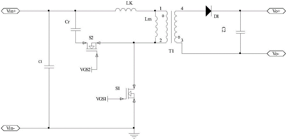
[0029] Such as Figure 4 As shown, it is the circuit schematic diagram of the active clamping flyback circuit of the present invention, the circuit adds a clamping diode D2 on the basis of the traditional active clamping flyback circuit, and the cathode of the clamping diode is connected to the terminal of S2 At the drain terminal, the anode of the clamp diode is connected to the bus terminal, and the diode is connected in parallel with the clamp capacitor.

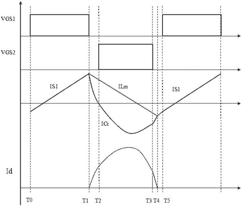
[0030] Such as Figure 5 As shown, it is the working waveform diagram of the active clamp flyback circuit of the present invention under full load. The specific working principle of the circuit is that at T0 time, the switch tube S1 is turned on, the input voltage is negatively demagnetized to the exciting inductor, and the exciting current After zero-crossing, it is positively excited, and the current flows from the voltage input terminal to the transformer and then flows through the switch tube S1. No current flows throu...

Embodiment 2

[0036] Such as Figure 10 As shown, it is the circuit schematic diagram of the specific embodiment 2 of the active clamping flyback circuit of the present invention. The difference between the active clamping flyback circuit of this embodiment and the first embodiment is that the The clamping diode was replaced with a TVS tube. Compared with the ordinary diode used in the first embodiment, the use of the TVS tube can not only realize the function of the ordinary diode to clamp the excitation inductance voltage, but also suppress the S1 drain voltage in a lower range, and use a smaller In this case, ensure that the drain-source voltage stress of S1 is within a safer range. Its working principle is the same as that in Embodiment 1, so it will not be repeated here.


PUM


Abstract

The invention relates to the field of switching converters, and particularly relates to a flyback active clamp-type switching converter control circuit and a control method thereof. The active clamp flyback circuit of the invention can realize reduced frequency and ZVS, and comprises a main power circuit, a clamp circuit, and an output rectification filter circuit, wherein a transformer and a main switching tube are connected to form the main power circuit; a clamp switching tube and a clamp capacitor and a clamp diode are connected to form the clamp circuit; and an output rectification diode and an output capacitor are connected to form the output rectification filter circuit. In comparison with the prior art, reduced frequency in light load can be realized, and the control scheme is flexible; switching loss in no load and loss of a transformer winding and switching tube inner resistance caused by a current effective value are little, no-load power consumption is greatly reduced, and the light-load efficiency is improved.

Description

technical field [0001] The invention relates to the field of switching converters, in particular to a control circuit and a control method of a flyback active clamp switching converter. Background technique [0002] With the rapid development of the field of power electronics, switching converters are used more and more widely, especially people put forward more requirements for switching converters with high power density, high reliability and small size. Generally, the traditional low-power AC / DC conversion is realized by the flyback topology, which has the advantages of simple structure and low cost; however, the ordinary flyback topology is a hard switch, and cannot recover leakage inductance energy, thus limiting the efficiency and efficiency of small and medium power products. In order to meet the development trend of miniaturization, light weight and modularization of power converters, soft switching technology has become one of the hot spots in power electronics tech...

Claims


Application Information

Patent Timeline
IPC IPC(8): H02M3/335
CPCH02M3/33569H02M1/0048H02M1/0054Y02B70/10
Inventor 赵永宁黄天华
Owner SHENZHEN NANYUN MICROELECTRONICS CO LTD
Why Eureka
Try Eureka