Supercharge Your Innovation With Domain-Expert AI Agents!

Main shaft device

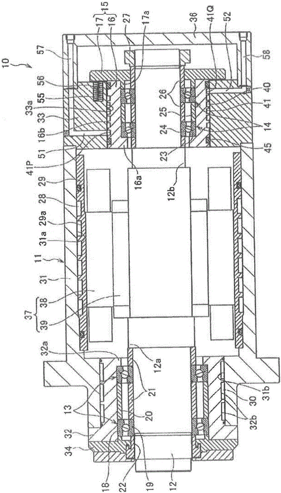
A technology for spindle devices and bearings, applied in electromechanical devices, shafts, cooling/ventilation devices, etc., can solve problems such as difficult to occur, and achieve the effects of preventing insufficient clearance, smooth flow, and high-efficiency cooling

Active Publication Date: 2016-10-26
NSK LTD
View PDF13 Cites 18 Cited by
  • Summary
  • Abstract
  • Description
  • Claims
  • Application Information

AI Technical Summary

Problems solved by technology

In addition, since the rear side bearing is the free side; and the degree of influence of thermal deformation on the machining accuracy of the rear of the spindle is smaller than that of the front side bearing (for example, even if the rotating shaft is relatively expanded in the axial direction with respect to the non-rotating element, The rear side of the spindle also slides backward, which is difficult to occur in the displacement of the front side of the spindle on which the tool is installed), etc. In most cases, no complicated cooling structure is added to the rear side bearing.

Method used


Image

  • Main shaft device
  • Main shaft device
  • Main shaft device

Examples


Embodiment 1

[0169] Here, the cooling structure of the first configuration example in which the cooling passage is provided on the outer peripheral surface of the bearing sleeve 16 and the cooling structure in which the cooling passage is provided on the outer peripheral surface of the rear housing are used. Figure 19 The cooling configuration shown, and the no-cooling configuration with no cooling paths provided on both the bearing sleeve and the rear housing, compare the temperature rise from the inner diameter of the bearing sleeve to the outer diameter of the housing. Figure 16 This is a graph comparing the temperature rise from the inner diameter of the bearing sleeve to the outer diameter of the housing due to the difference in cooling structure.

[0170] From Figure 16 It can be seen that the cooling structure of the present invention in which the cooling passage 40 is provided on the outer peripheral surface of the bearing sleeve 16 has the smallest temperature rise among the te...

Embodiment 2

[0176] Next, the cooling structure of the second configuration example in which the cooling passage is provided on the outer peripheral surface of the bearing sleeve 16 and the cooling structure in which the cooling passage is provided on the outer peripheral surface of the rear housing are used. Figure 19 The cooling configuration shown, and the no-cooling configuration with no cooling paths provided on both the bearing sleeve and the rear housing, compare the temperature rise values ​​from the inner diameter of the bearing sleeve to the outer diameter of the housing. Figure 17 This is a graph comparing the temperature rise from the inner diameter of the bearing sleeve to the outer diameter of the housing due to the difference in cooling structure.

[0177] From Figure 17 It can be seen that the cooling structure of the present invention in which the cooling passage 40 is provided on the outer peripheral surface of the bearing sleeve 16 has the smallest temperature rise am...


PUM


Abstract

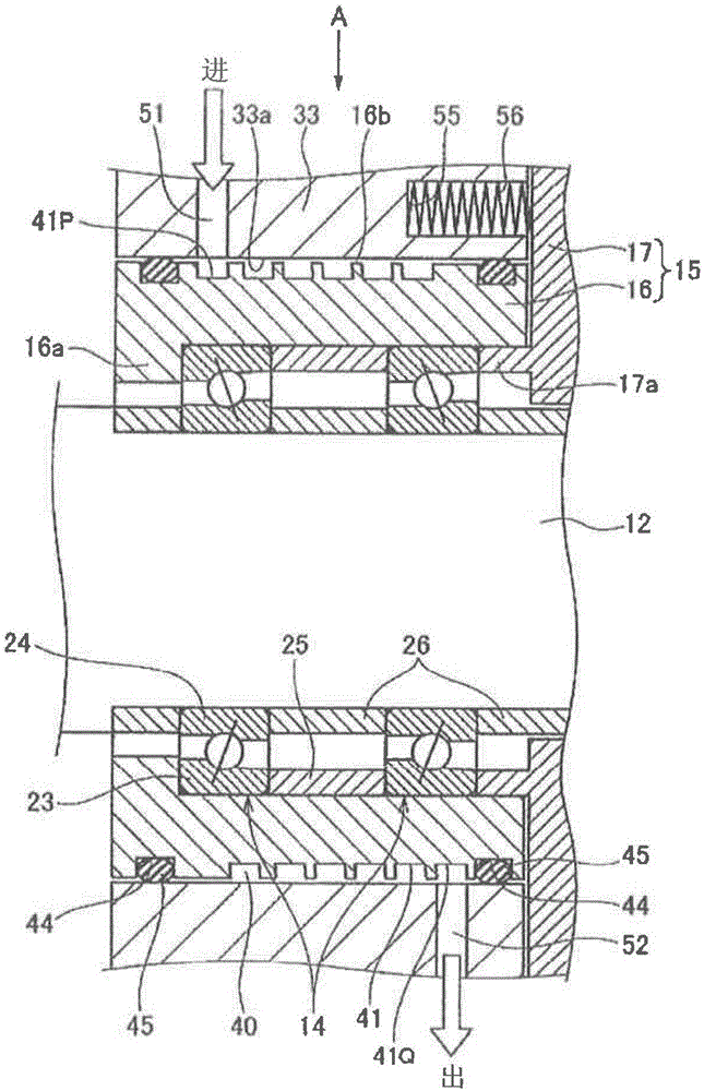
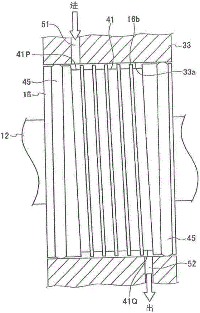
A cooling passage through which a cooling medium can flow is formed between the inner peripheral surface of a rear housing, and the outer peripheral surface of a bearing sleeve having a free-side bearing inserted therein. The cooling passage is formed in the outer peripheral surface of the bearing sleeve, and comprises one or a plurality of helical grooves formed in the outer peripheral surface of the sleeve from one-end side of the sleeve in the axial direction to another-end side of the sleeve in the axial direction. The housing is provided with: a supply port which communicates with one end of the helical grooves, and through which the cooling medium is supplied; and a discharge port which communicates with another end of the helical grooves, and through which the cooling medium that has flowed through the cooling passage is discharged.

Description

technical field [0001] The present invention relates to a spindle device, and more specifically, to a spindle device of a high-speed rotating machine such as a machine tool spindle, a high-speed motor, a centrifugal separator, or a turbo refrigerator. Background technique [0002] The increase in the speed of the spindle of the machine tool has progressed remarkably, and oil-air lubrication and oil-mist lubrication have been used as lubrication methods for increasing the spindle speed. In addition, as another lubricating method, from the viewpoint of environmental protection, grease lubrication, which does not discharge lubricating oil to the outside, has been newly recognized again, and the rolling bearings used are made of lightweight ceramics with excellent burn resistance under high-speed rotation. Rolling elements (such as silicon nitride, etc.). [0003] In addition, as a driving method for a high-speed rotating spindle, there are more so-called built-in motor spindle...

Claims


Application Information

Patent Timeline
IPC IPC(8): F16C37/00B23B19/02B23Q11/12H02K9/19
CPCF16C2322/39B23Q11/127F16C35/077F16C35/12F16C37/007H02K5/1732F16C19/546H02K5/203F16C2300/22F16C19/547H02K9/19
Inventor 小栗翔一郎胜野美昭
Owner NSK LTD
Features
  • R&D
  • Intellectual Property
  • Life Sciences
  • Materials
  • Tech Scout
  • Unparalleled Data Quality
  • Higher Quality Content
  • 60% Fewer Hallucinations
Learn More