A solvent oil gas recovery device
A recovery device, oil and gas technology, applied in combination device, grease/oily substance/float removal device, immiscible liquid separation, etc., can solve the problem of unsatisfactory gas treatment effect, difficult maintenance life, poor solvent recovery effect, etc problem, to achieve the effect of convenient disassembly and washing function, long service life, and improved processing and recycling efficiency
- Summary
- Abstract
- Description
- Claims
- Application Information
AI Technical Summary
Problems solved by technology
Method used
Image
Examples
Embodiment 1
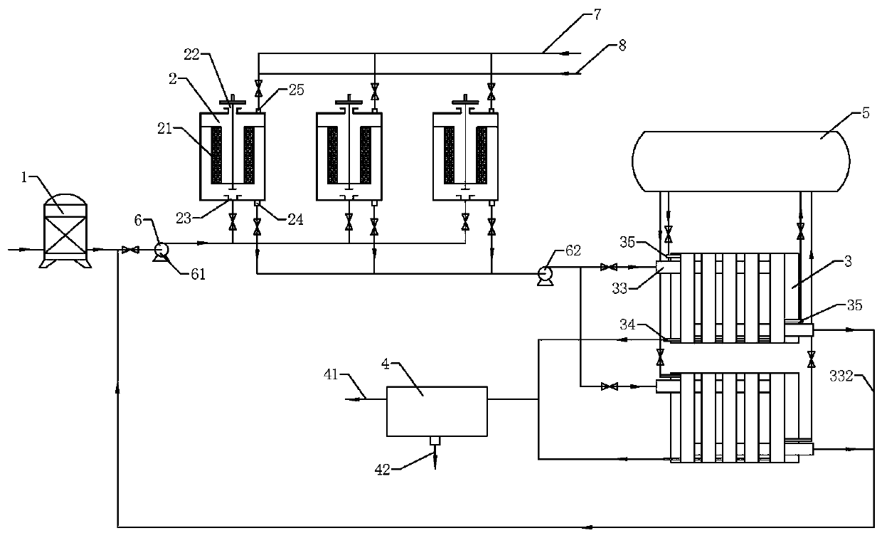
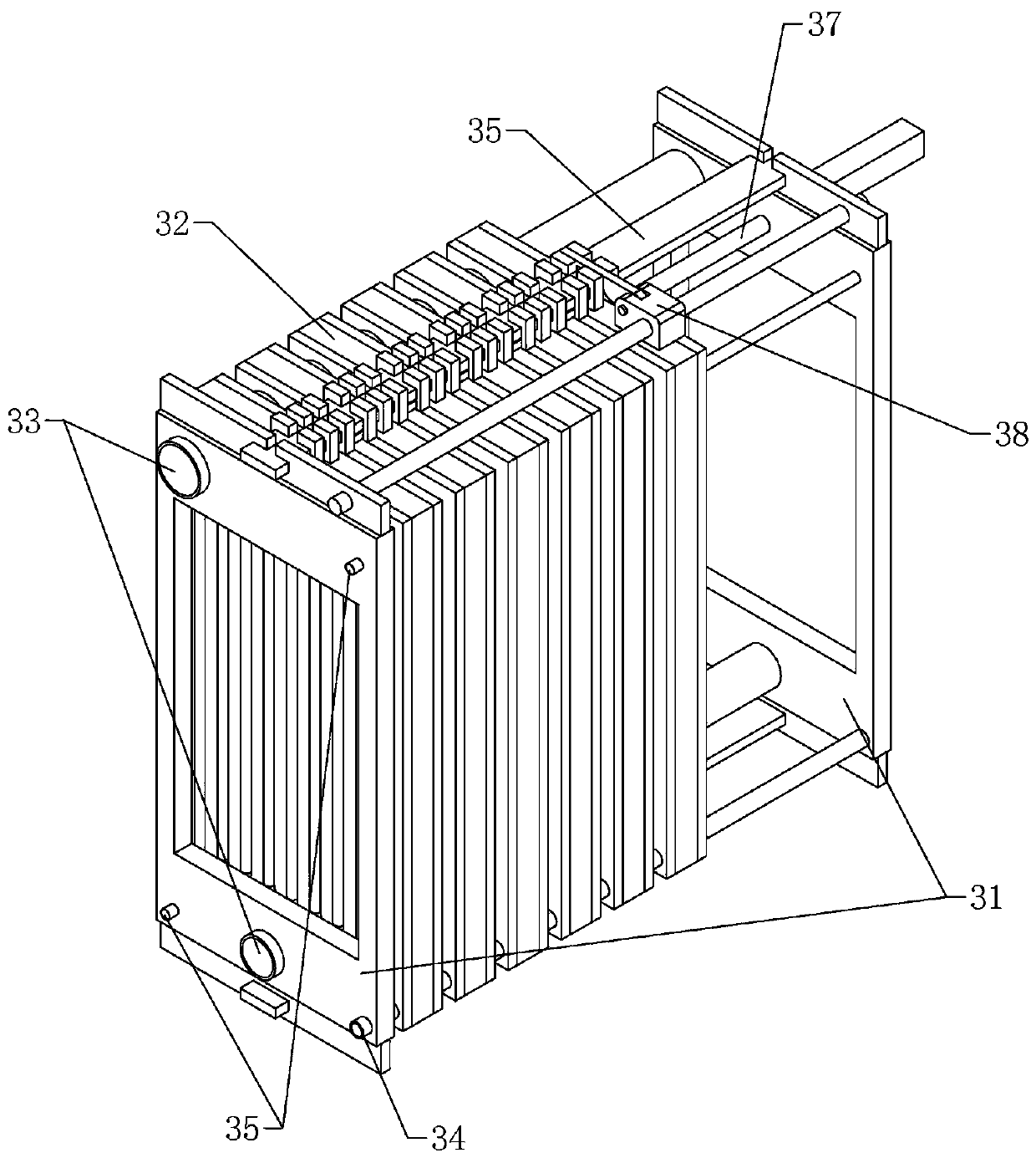
[0040] according to Figure 1 to Figure 8 As shown, a solvent oil gas recovery device includes: a coarse filter 1, an adsorption tank 2, two parallel condensation filters 3, an oil-water separator 4, a refrigerator 5, a fan 6, a steam pipeline 7 and a hot gas pipeline 8, and the steam The temperature of the steam in the pipeline 7 is 100-200°C, the temperature of the hot gas in the hot-gas pipeline 8 is 60-100°C, and the temperature in the condensation filter 3 is controlled at -10-5°C;
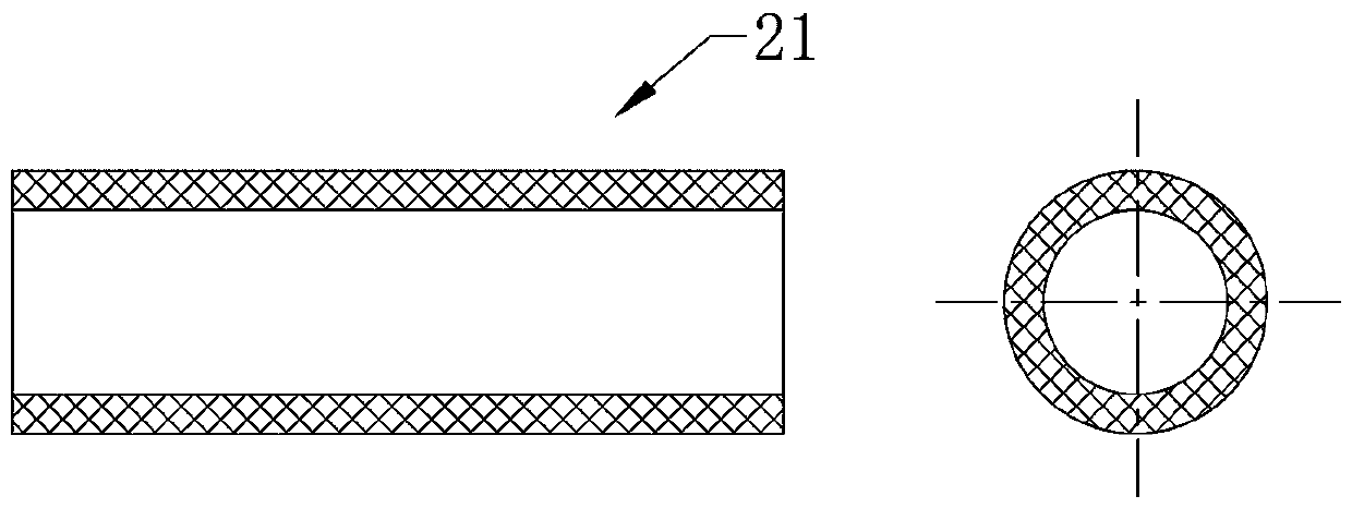
[0041] The number of adsorption tanks 2 is 3, which are set in the way of one desorption and two suctions. Each adsorption tank 2 includes a fiber activated carbon layer 21, a purified gas outlet 22, a waste gas inlet 23 connected with the coarse filter 1, and a desorption gas outlet 24. And the desorption gas inlet 25, the desorption gas outlet 24 is communicated with the condensation filter 3, the desorption gas inlet 25 is communicated with the steam pipeline 7 and the hot gas pipeline 8, ...
Embodiment 2
[0055] The difference from the above-mentioned embodiment 1 is that, according to image 3 , Figure 4 As shown, a separation mechanism 38 is also provided on the shelf plate 31, the separation mechanism 38 includes a slide bar 381 and a separator 382, the slide bar 381 is a screw rod, and the separator 382 includes a slide table 3821 and a hinged joint arranged on the slide bar 381. The driving rod 3822 on the slide table 3821 is controlled by the motor provided on the slide table 3821, and can rotate up and down, thereby selecting the slide block 326 to move.
[0056] In the device cleaning process of this embodiment, the difference from Embodiment 1 is that when the device is cleaned, after the pressure rod 371 is loosened, the first filter plate 32a, the second filter plate 32b and the sealing backing plate of the condensation filter unit 32 32c are separated one by one under the drive of separation mechanism 38, which saves manpower.
Embodiment 3
[0058] The difference from the above-mentioned embodiment 2 is that, according to Figure 7 As shown, the slide bar 381 is also provided with a backwash spray head 39 that can slide along the slide bar 381. The backwash spray head 39 includes a mobile platform 391, a spray bar 392 hinged on the mobile platform 391 and a spray bar connected to the mobile platform 391. Water inlet pipe 393. After the first filter plate 32a, the second filter plate 32b and the sealing backing plate 32c of the condensation filter unit 32 are separated under the action of the separation mechanism 38, they are cleaned by the backwash nozzle 39, which improves the automation of the equipment.
PUM
 Abstract
Description
Claims
Application Information
 - R&D
- Intellectual Property
- Life Sciences
- Materials
- Tech Scout
- Unparalleled Data Quality
- Higher Quality Content
- 60% Fewer Hallucinations
Browse by: Latest US Patents, China's latest patents, Technical Efficacy Thesaurus, Application Domain, Technology Topic, Popular Technical Reports.
© 2025 PatSnap. All rights reserved.Legal|Privacy policy|Modern Slavery Act Transparency Statement|Sitemap|About US| Contact US: help@patsnap.com


