Apparatus and method for lifting up, compacting and forming concrete in steel-pipe column (wall)

A technology for a concrete roof and forming device, which is applied to columns, walls, piers and other directions, can solve the problems of discontinuous concrete, heavy vibrating work, complicated construction organization, etc. , pumpability and ease of flow

Inactive Publication Date: 2016-11-02
NANTONG CONSTR PROJECT GENERAL CONTRACTING
View PDF10 Cites 3 Cited by
  • Summary
  • Abstract
  • Description
  • Claims
  • Application Information

AI Technical Summary

Problems solved by technology

The construction speed of this method is slow, and the construction organization is complicated, and the vibration work is heavy, so it is widely used in the early steel pipe column (wall) concrete construction; the second is the high-level drop-free vibration method
Utilize the kinetic energy of commercial concrete falling along the steel pipe from high altitude to achieve the purpose of compacting commercial concrete, which can save or reduce the heavy vibration work, but this method is suitable for the situation where the pipe diameter is not less than 300mm and the height is not more than 5m, and it is easy to cause The core commercial concrete is discontinuous, poor in integrity, and not easy to vent; the third is the pumping jacking pouring method

Method used


Image

  • Apparatus and method for lifting up, compacting and forming concrete in steel-pipe column (wall)
  • Apparatus and method for lifting up, compacting and forming concrete in steel-pipe column (wall)
  • Apparatus and method for lifting up, compacting and forming concrete in steel-pipe column (wall)

Examples


Embodiment Construction

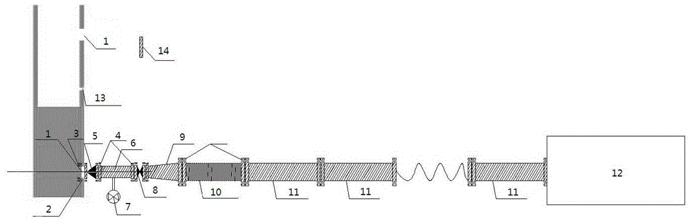
[0042] The present invention will be further described below in conjunction with accompanying drawing:

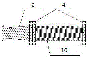
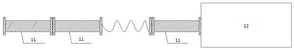
[0043] A steel pipe column (wall) concrete jacking and compacting forming device, including a pressing structure node, an anti-backflow device, a pressure regulating device, and a pumping system;

[0044] The binder structure node is arranged on the bottom side of the steel pipe column (wall), and the binder structure node is sequentially connected to the anti-backflow device, the pressure regulating device, and the pumping system.

[0045] Further, the binder structure node is a material injection hole (1) arranged on the bottom side of the steel pipe column (wall), and a bolt connection hole (2) with silk thread is provided on the steel plate around the material injection hole (1) A connecting nut (3) is welded on the inner side of the steel pipe column (wall), and the connecting nut (3) is connected to the connecting flange (4) of the anti-backflow device through connect...


PUM


Abstract

The invention provides an apparatus and a method for lifting up, compacting and forming concrete in a steel-pipe column (wall). The apparatus comprises the following components: a material pressing structure node, a counter current preventing apparatus, a pressure regulating apparatus, and a pumping system; the material pressing structure node is arranged at the side surface of the bottom of the steel-pipe column (wall), and the material pressing structure node is connected to the counter current preventing apparatus, the pressure regulating apparatus, and the pumping system in order. The pumping system is used, a pressure conveying principle is used in order to lift concrete from the bottom of the steel-pipe column (wall) to the top of the column (wall), and the concrete is compacted and formed in the steel-pipe column (wall) by pressure. The apparatus and the method for lifting up, compacting and forming concrete in the steel-pipe column (wall) use local materials for processing and producing, pressure in a transfer pump is used for carrying out the lifting-up work for the concrete, so that the common concrete reaches effects of self-compaction concrete, and the apparatus and the method have the advantages of substantially reduced construction cost, simple operation, good quality, low cost, and substantial economic effects; the apparatus and the method can be applied to concrete construction of various steel-pipe columns (walls) with application and promotion values.

Description

technical field [0001] The invention relates to a construction measure device, in particular to a steel pipe column (wall) concrete jacking and compacting forming device and method. Background technique [0002] There are three main methods of concrete pouring for steel pipe columns (walls): one is manual pouring and pounding. The construction speed of this method is slow, and the construction organization is complicated, and the vibration work is heavy. It is widely used in the early concrete construction of steel pipe columns (walls). The second is the high-level drop-free vibration method. Utilize the kinetic energy of commercial concrete falling along the steel pipe from high altitude to achieve the purpose of compacting commercial concrete, which can save or reduce the heavy vibration work, but this method is suitable for the situation where the pipe diameter is not less than 300mm and the height is not more than 5m, and it is easy to cause The core commercial concrete...

Claims


Application Information

Patent Timeline
Patent Type & Authority Applications(China)
IPC IPC(8): E04C3/34E04B2/86E04G21/02
CPCE04B2/86E04C3/34E04G21/02
Inventor 袁秦标孙瑞先袁美翠吴伟杰庞成建何健
Owner NANTONG CONSTR PROJECT GENERAL CONTRACTING
Why Eureka
Try Eureka