Ultra-large environment-friendly and energy-efficient drying box
A high-efficiency, energy-saving, super-large technology, applied in drying, dryer, drying of solid materials, etc., can solve the problems of small capacity and low thermal efficiency of natural gas drying box, save electric energy and heat, improve combustion temperature, The effect of reducing the floor space
- Summary
- Abstract
- Description
- Claims
- Application Information
AI Technical Summary
Problems solved by technology
Method used
Image
Examples
Embodiment 1
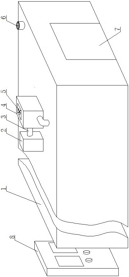
[0042]The super-large environment-friendly, high-efficiency and energy-saving drying box of the present invention includes an electric control cabinet 8, a box body 1, a burner 2, a combustion chamber 4 and a controller 20, the controller 20 is arranged in the electric control cabinet 8, the burner 2 and the combustion chamber The chambers 4 are all arranged above the outside of the box body 1. The box body 1 is an insulated box body composed of insulation boards. The box body 1 is provided with two doors 7. On the side wall, each door 7 is an electric control door, and each door 7 is connected with a controller 20 .
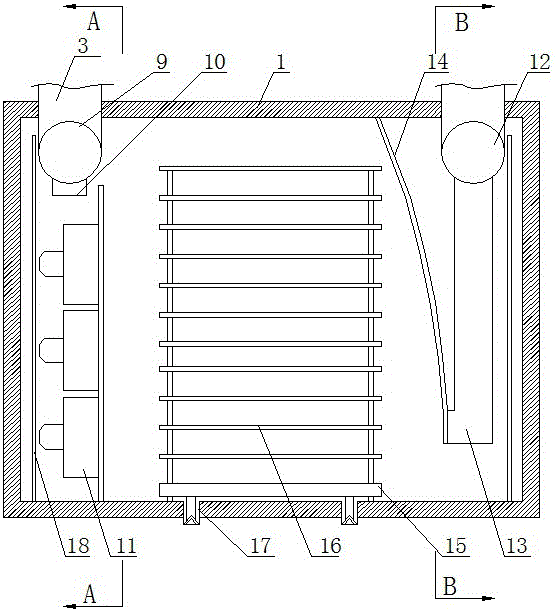
[0043] The inside of the cabinet 1 is provided with an air inlet pipe 9, an air outlet pipe 12, a metal plate, a guide rail 17, a drying cart 15 and a plurality of stirring fans 11, and the drying cart 15 is provided with a frame that can place multi-layer drying loads 16. The air inlet duct 9 is arranged on the top of the front side of the box body 1, and the ...
Embodiment 2
[0062] This embodiment is a further improvement on the basis of Embodiment 1, and the difference between this embodiment and Embodiment 1 is:
[0063] A heat exchanger 27 is arranged above the outer top of the box body 1. The heat exchanger 27 includes an inlet I29, an outlet I30, an inlet II32, and an outlet II31. An induced draft fan 28 is arranged at the inlet I29, and the outlet I30 passes through the air inlet of the combustion chamber 4. The pipe 3 is connected, the fresh fan 5 is located on the pipe 3 between the air inlet of the combustion chamber 4 and the outlet I30, the pipe 3 connected with the outlet pipe 12 is connected to the inlet II32, and the exhaust fan 6 is located between the outlet pipe 12 and the inlet II32 On the pipe 3 between; inlet I29, outlet I30, combustion chamber 4, air inlet pipe 9, multiple air inlets 10 on the air inlet pipe 9, multiple air outlet pipes 13 on the air outlet pipe 12, air outlet The pipeline 12 , the inlet II 32 and the outlet I...
PUM
 Abstract
Description
Claims
Application Information
 - R&D
- Intellectual Property
- Life Sciences
- Materials
- Tech Scout
- Unparalleled Data Quality
- Higher Quality Content
- 60% Fewer Hallucinations
Browse by: Latest US Patents, China's latest patents, Technical Efficacy Thesaurus, Application Domain, Technology Topic, Popular Technical Reports.
© 2025 PatSnap. All rights reserved.Legal|Privacy policy|Modern Slavery Act Transparency Statement|Sitemap|About US| Contact US: help@patsnap.com


