Target suitable for fast scanning scene and extraction method of target control point

A fast scanning and extraction method technology, applied in the direction of optical devices, image data processing, measuring devices, etc., can solve the problems of not being able to scan point cloud data information at one time, difficult production, large scanning errors, etc., to improve computing High efficiency and accuracy, high applicability and reliability, and the effect of improving production accuracy

Active Publication Date: 2016-11-02
XIAMEN UNIV
View PDF6 Cites 15 Cited by
  • Summary
  • Abstract
  • Description
  • Claims
  • Application Information

AI Technical Summary

Problems solved by technology

[0005] Traditional targets are mainly spherical targets, cylindrical targets and planar targets. Among them, spherical targets and cylindrical targets have the following disadvantages: 1. Both require surface fitting, which requires a large amount of data calculation and low efficiency; 2. In-vehicle or machine In the application scenario of on-board scanning, due to the high-speed operation characteristics of the carrier platform, the point cloud data that can be scanned is extremely limited, and the point cloud data required for fitting the surface is large, which limits its application; 3. Making spherical targets and cylinders When the target size is too small, it is impossible to collect all the surface point cloud data information at one time. If the target size is too large, it will be difficult to manufacture. The obtained spherical or cylindrical surface is low-precision, and the scanning error is large.
The disadvantage of the planar target is that the accuracy of the control points of the planar target is affected by multiple reflection effects and the accuracy is low

Method used


Image

  • Target suitable for fast scanning scene and extraction method of target control point
  • Target suitable for fast scanning scene and extraction method of target control point
  • Target suitable for fast scanning scene and extraction method of target control point

Examples


Embodiment

[0049] The present embodiment will be described in detail below in conjunction with the accompanying drawings.

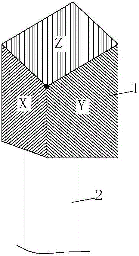
[0050] Such as figure 1As shown, the three-plane target includes a target 1 and a connecting column 2. The connecting column 2 lifts the target 1 off the ground to obtain a suitable height for scanning by the laser scanning system, and under the action of the connecting column 2, the target 1. It avoids the interference objects that may exist in the background area, and facilitates the identification and extraction of the point cloud data belonging to the target in the scanned point cloud data. The target surface of the target 1 is composed of three non-parallel planes X, Y, and Z. The X, Y, and Z planes intersect at one point, which is the control point of the target. The angle between the X and Y planes is an obtuse angle, and the angle between the intersection line of the X and Y planes and the Z plane is also an obtuse angle, which is beneficial to increase the...


PUM


Abstract

The invention discloses a target suitable for a fast scanning scene and an extraction method of a target control point. The target is composed of a plane X, a plane Y and a plane Z which are not parallel to one another; and the target surface of the target is coated with silver white paint. The method includes the following steps that: S1, a laser scanning system is adopted to scan the target and carry out coordinate calculation on obtained point cloud data; S2, target point cloud data in three-dimensional point cloud data are identified and intercepted, so that point cloud subspaces can be obtained; S3, plane model estimation is carried out the point cloud subspaces, denoising is carried out by using the dichotomy, so that basic point cloud can be obtained, and noises are eliminated; S4 iterative denoising processing is performed on the basic point cloud, and accurate plane parameters can be obtained; and S5, the obtained parameters are adopted to build a nonhomogeneous linear equation set, and the target control point can be solved. The target and the extraction method of the target control point are suitable for scenes where carrier platforms move fast. With the method adopted, the coordinates of the target control point in point cloud can be quickly and accurately determined, and therefore, the accuracy of point cloud data can be improved. The method has a high application value.

Description

technical field [0001] The invention relates to the field of precise positioning of point cloud data, in particular to a method for extracting targets and control points suitable for fast scanning scenes. Background technique [0002] Three-dimensional laser scanning technology is an emerging technology. The use of three-dimensional laser scanning technology to collect data has many advantages such as high efficiency, large amount of data, and fast speed. It has become an important technical means to record the spatial distribution and surface characteristics of the environment, and is widely used in For engineering surveying, power line inspection, track monitoring, forest survey and other purposes, depending on the carrier platform, there are mainly airborne, vehicle-mounted and terrestrial laser scanning. [0003] There are many factors that affect the accuracy of point cloud data obtained by 3D laser scanning technology, including target control point fitting error, GPS ...

Claims


Application Information

Patent Timeline
Patent Type & Authority Applications(China)
IPC IPC(8): G01B11/00G01B11/24G06T5/00
CPCG01B11/002G01B11/24G06T5/002
Inventor 王程程明李军
Owner XIAMEN UNIV
Why Eureka
Try Eureka