Loaded continuous catalytic column, multi-flux loaded catalytic continuous reaction equipment and its application
A technology of reaction equipment and catalyst loading, which is applied in the field of continuous catalytic reaction, can solve the problems affecting the reaction yield and flexibility of use of fixed bed reactors, the inability to ensure uniform distribution of catalysts, and inconvenient replacement, so as to achieve low liquid holding capacity and equipment Small footprint and the effect of preventing local hot spots
- Summary
- Abstract
- Description
- Claims
- Application Information
AI Technical Summary
Problems solved by technology
Method used
Image
Examples
Embodiment 1
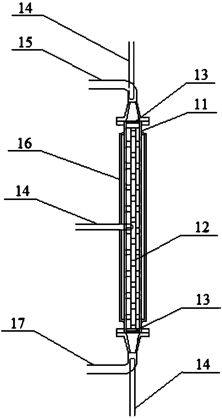
[0050] Such as figure 1 Shown, a kind of load continuous catalytic column that can be used for continuous reaction system, comprises column body 11, load catalyst distributor 12, gas-liquid distributor 13; Outlet pipe 15; inside the cylinder, in the direction from the inlet pipe 17 to the outlet pipe 15, a gas-liquid distributor 13, a loaded catalyst distributor 12, and a gas-liquid distributor 13 are respectively installed;
[0051] The diameters of the inlet pipe 17 and the outlet pipe 15 are all less than the diameter of the cylinder 11, the inlet pipe 17 is arranged at the bottom of the catalytic column, and the outlet pipe 15 is arranged at the top of the catalytic column;
[0052] Preferably, the material of the cylinder 11 is selected from: metal, alloy, plastic, more preferably from: stainless steel, Hastelloy and polytetrafluoroethylene; the outer diameter of the cylinder 11 is 2-150mm, preferably 3~100mm;
[0053] Preferably, the inner wall roughness of the cylinde...
Embodiment 2
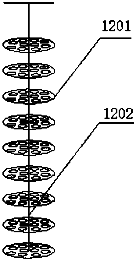
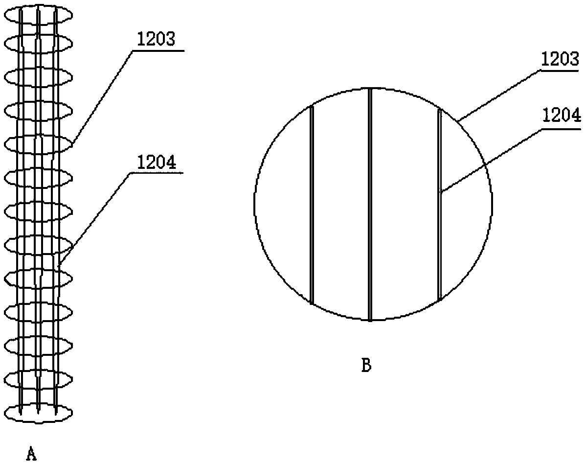
[0058] figure 1 The loaded catalyst distributor 12 includes more than two loaded catalyst distribution plates and a fixed connection mechanism. The described distribution plate is used for loading the loaded catalyst and is circular with a diameter smaller than the inner diameter of the column. The number of layers of the distribution plate can be adjusted according to the needs. Responsible for increasing or decreasing the amount of catalyst, and adjusting the opening ratio according to the particle size of the loaded catalyst to ensure that the loaded catalyst does not fall or flow out with the material, and the pressure drop of the material in and out is within 0.5MPa. The fixed connection mechanism is used to connect and fix the distribution plate; in the catalytic column, the distribution plate is perpendicular to the diameter direction of the cylinder and distributed in layers along the diameter direction.
[0059] Described loaded catalyst distributor 12 can be basket t...
Embodiment 3
[0065] Such as Figure 4 As shown, a multi-flux loaded catalytic continuous reaction equipment includes the above-mentioned loaded continuous catalytic column 1 and an automatic feeding system; the loaded continuous catalytic column 1 is connected to the automatic feeding system; the loaded continuous catalytic column can be passed through a multi-pass Valve 3 is connected with automatic feeding system; Described automatic feeding system comprises electronic weighing device 21, feeding pump 22 (as plunger pump), single-chip microcomputer 23, single-chip microcomputer 23 and electronic weighing device 21 and feeding pump 22 Connection control, the reaction material is placed on the electronic weighing device 21, and the feeding is realized after the feeding pump 22 is turned on. After collecting the data of the electronic weighing device 21 and calculating by the single-chip microcomputer 23, the flow rate of the feeding pump 22 is controlled to achieve accurate and stable mater...
PUM
 Abstract
Description
Claims
Application Information
 - R&D
- Intellectual Property
- Life Sciences
- Materials
- Tech Scout
- Unparalleled Data Quality
- Higher Quality Content
- 60% Fewer Hallucinations
Browse by: Latest US Patents, China's latest patents, Technical Efficacy Thesaurus, Application Domain, Technology Topic, Popular Technical Reports.
© 2025 PatSnap. All rights reserved.Legal|Privacy policy|Modern Slavery Act Transparency Statement|Sitemap|About US| Contact US: help@patsnap.com


