Method for controlling crack formation in heat affected zones in nickel-based alloy multi-layer laser filler wire welding

A heat-affected zone and laser wire filling technology, applied in laser welding equipment, manufacturing tools, welding equipment, etc., can solve the problem of changing the stress distribution of joints, reducing the formation rate of liquefaction cracks in the heat-affected zone, and reducing the high temperature residence time in the heat-affected zone, etc. problem to avoid stress concentration

Active Publication Date: 2016-11-09
SHANGHAI JIAO TONG UNIV
View PDF13 Cites 7 Cited by
  • Summary
  • Abstract
  • Description
  • Claims
  • Application Information

AI Technical Summary

Problems solved by technology

[0005] The invention aims to solve the problem that cracks are prone to appear in the heat-affected zone in nickel-based alloy laser wire repair welding or butt welding. By controlling the heat input of the weld seam, the secondary heat of the heat-affected zone can be avoided, and the high-temperature residence time of the heat-affected zone can be reduced. At the same time, by controlling the laser defocus, the welding seam is c

Method used


Image

  • Method for controlling crack formation in heat affected zones in nickel-based alloy multi-layer laser filler wire welding
  • Method for controlling crack formation in heat affected zones in nickel-based alloy multi-layer laser filler wire welding

Examples


Embodiment

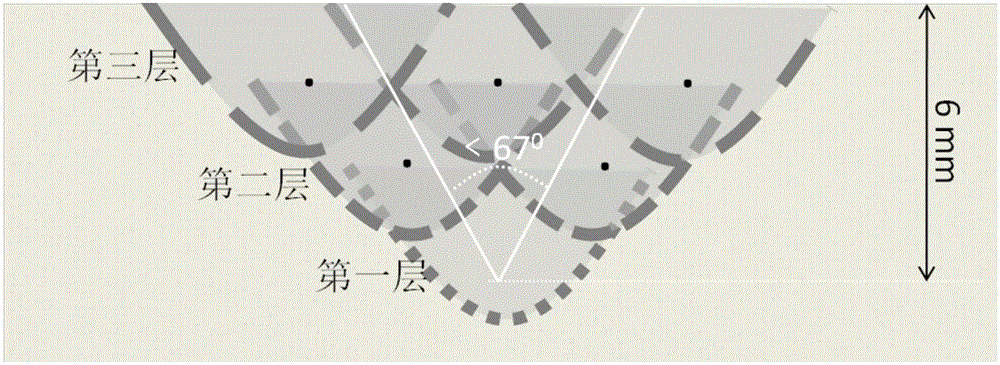
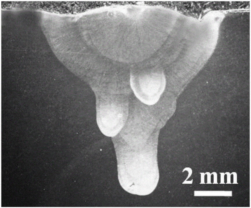
[0032] A method for controlling the formation of liquefaction cracks in the heat-affected zone of nickel-based alloy multilayer laser wire-filled welding, please refer to figure 1 As shown, the cross-sectional morphology of the sample after welding is as follows figure 2 shown.

[0033] This implementation case is butt welding, in which the plate to be welded is 718 nickel-based alloy, and the thickness of the welded plate is 10mm. Using CO 2 Laser wire filling welding method, the filler material is consistent with the composition of 718 alloy, the shielding gas is pure He, the gas flow rate is 30L / min, the laser output power is 6kW, the welding speed is 1.5m / min, and the wire feeding speed is 3m / min. The focal weight is +20mm, and the heat input is 4J / mm.

[0034] The welding process includes the following steps:

[0035] The first step is to process into figure 1 For the groove sample shown, the angle of the processed V-shaped groove is less than 67°, and the depth of ...


PUM

PropertyMeasurementUnit
Depthaaaaaaaaaa
Upper surface widthaaaaaaaaaa
Plate thicknessaaaaaaaaaa

Abstract

The invention discloses a method for controlling liquefied crack formation in heat affected zones in nickel-based alloy laser multi-layer filler wire welding. The method is mainly suitable for the welding process of welding and repair welding of nickel-based alloy laser filler wires with the thickness ranging from 3 mm to 12 mm. According to the method, the main principle is that joint stress distribution is changed, and the high-temperature dwell time of the heat affected zones of the overlapped positions is shortened, so that the crack formation rate is lowered. The welding method mainly comprises the following steps that firstly, the appropriate laser welding defocusing amount is determined, so that the fusion line of the cross section of each of weld joints is in a circular arc shape or an oval arc shape; and secondly, after the primary weld joint process is completed, in the secondary welding process, the heat affected zones generated in primary welding are made to be located in weld joint regions generated in the secondary welding process, and so on, the follow-up weld joints are treated. By the adoption of the welding method, under the same condition, the crack rate is lower compared with common laser filler wire repair welding or laser filler wire thick plate welding.

Description

technical field [0001] The invention belongs to the technical field of nickel-base alloy multi-layer laser wire-fill welding, and mainly relates to a connection method for butt welding of nickel-base alloy plates less than 12 mm thick, in particular to a laser wire-fill repair welding method for nickel-base alloy casting defects. Background technique [0002] High-temperature nickel-based alloys are widely used in important large-scale components such as steam turbines, engines, turbine disks, and blades because of their good mechanical properties, good high-temperature oxidation resistance, corrosion resistance, and good thermal stability in high-temperature environments. These large components will have a certain degree of defects and damage during the casting process or in the high-temperature service environment, so they must be repaired or replaced in time, but when the damaged area is small, replacing the entire component will not only increase the cost, but also Incre...

Claims


Application Information

Patent Timeline
IPC IPC(8): B23K26/20B23K26/04B23K26/32B23K103/08
CPCB23K26/04B23K26/20B23K26/32B23K2103/08
Inventor 崔海超芦凤桂唐新华
Owner SHANGHAI JIAO TONG UNIV
Why Eureka
Try Eureka