Sand blasting machine

A technology of sandblasting machine and sandblasting room, which is applied in the field of sandblasting machines, can solve the problems of low efficiency of picking and placing workpieces, difficulty in controlling the accuracy of workpieces, uneven sandblasting, etc., and achieve the goal of improving sandblasting efficiency and sandblasting quality Effect

Active Publication Date: 2016-11-09
宁波精益微型轴有限公司
View PDF6 Cites 13 Cited by
  • Summary
  • Abstract
  • Description
  • Claims
  • Application Information

AI Technical Summary

Problems solved by technology

[0004] However, in the prior art, when sandblasting large-scale workpieces such as wheel hubs, most of them manually enter the blasting chamber for sandblasting, and a single blasting head is used for sandblasting. When the workpiece is sandblasting, most of the workpieces are manually entered into the sandblasting room to pick and place the workpiece. Not only is it difficult to control the accuracy of the workpiece placement, but the efficiency of picking and placing the workpiece is also very low.

Method used


Image

  • Sand blasting machine
  • Sand blasting machine
  • Sand blasting machine

Examples


Embodiment 1

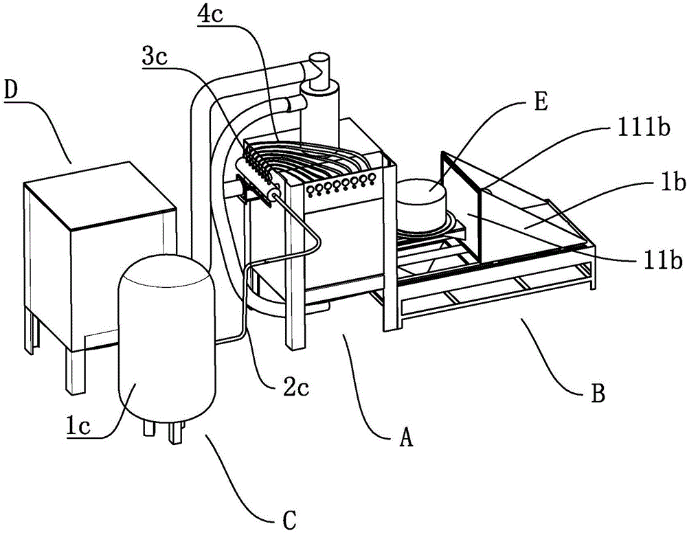
[0041] Embodiment one, a kind of sand blasting machine, take wheel hub E as the workpiece of processing, see attached figure 1 , the sandblasting machine includes a sandblasting part A, a feeding mechanism B, an air intake mechanism C and a dust removal mechanism D, and a sand storage part 2a is arranged on the top of the sandblasting part A, and the upper part of the sand storage part 2a is connected with a cyclone separator Afterwards, the dust removal mechanism D is connected through a pipeline; the air intake mechanism C is mainly the gas source pump 1c, and the gas source pump 1c inputs high-pressure gas into the gas transfer tank through the gas main pipe 2c, and eight pressure regulating valves 3c are arranged on the gas transfer tank , and then through the pressure regulating valve 3c, eight gas branch pipes 4c are connected to cooperate with the nozzle 4a. See attached Figure 4 , the top of the sandblasting chamber 1a is provided with a sand storage part 2a, the bot...

Embodiment 2

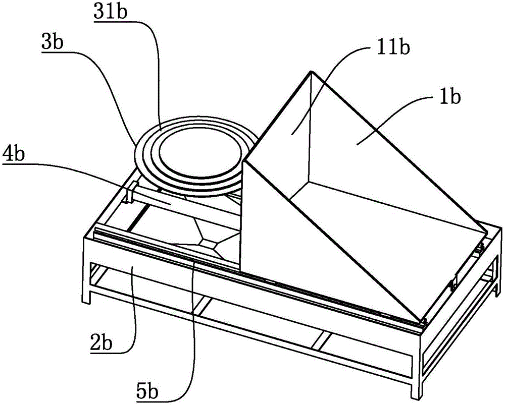
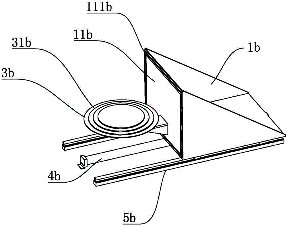
[0047] Embodiment two, a kind of sandblasting machine, see the appendix for the difference with embodiment one Figure 9 and 10 , a second motor 6b is provided at the placement platform 1b, the positioning table 3b is rotationally connected with the placement platform 1b, a rotating base 32b is provided at the bottom of the positioning table 3b, and a belt pulley 7 is set between the second motor 6b and the rotating base 32b, thereby Drive the positioning table 3b to rotate.

[0048] Thereby when working, will produce following difference and effect: in the process of sandblasting, second motor 6b drives positioning table 3b to rotate through belt pulley 7, and wheel hub E will also rotate in sandblasting chamber 1a simultaneously, and spray nozzle 4a sprays on When it is on the hub E, it is more uniform, and the sandblasting uniformity and sandblasting quality are improved.


PUM


Abstract

The invention discloses a sand blasting machine, which comprises a sand blasting chamber. The sand blasting chamber comprises a feeding hole for feeding and discharging workpieces, and spray nozzles arranged in the sand blasting chamber; the spray nozzles are fixed on a spray nozzle drive mechanism; a feeding mechanism capable of driving the workpieces to feed and discharge is matched on the feeding hole; the spray nozzle drive mechanism comprises at least one swinging mechanism arranged in the sand blasting chamber; each swinging mechanism is provided with one spray nozzle and is driven by a first drive part to swing to the left and right; the feeding mechanism comprises a placement platform used for placing workpieces and a second drive part; and the placement platform comprises at least one positioning table used for placing the workpieces, and a sealing plate arranged behind the positioning table and matched with the feeding hole of the sand blasting chamber. A plurality of swinging mechanisms are arranged in the sand blasting chamber, and a plurality of spray nozzles can swing to blast sand on the workpieces when being used for blasting sand, so that a uniform and efficient sand blasting effect is realized; and in addition, the workpieces can be quickly fed and discharged in the sand blasting chamber through the feeding mechanism, so that the sand blasting efficiency of the workpieces is further improved.

Description

technical field [0001] The invention relates to the field of painting equipment, more specifically, it relates to a sandblasting machine. Background technique [0002] Sand blasting uses compressed air as the power to form a high-speed jet beam to spray materials: copper ore, quartz sand, corundum, iron sand, Hainan sand, etc., to the surface of the workpiece to be treated at high speed, so that the outer surface of the workpiece surface looks smoother. or change in shape. Due to the impact and cutting effect of the abrasive on the surface of the workpiece, the surface of the workpiece can obtain a certain degree of cleanliness and different roughness, so that the mechanical properties of the surface of the workpiece can be improved, the fatigue resistance of the workpiece can be improved, and the gap between the workpiece and the coating can be increased. Excellent adhesion, prolonging the durability of the coating film, and also conducive to the leveling and decoration of...

Claims


Application Information

Patent Timeline
Patent Type & Authority Applications(China)
IPC IPC(8): B24C3/32B24C5/02B24C7/00B24C9/00
CPCB24C3/32B24C5/02B24C7/0046B24C9/003B24C9/006
Inventor 董祥义过志强
Owner 宁波精益微型轴有限公司
Why Eureka
Try Eureka