Coolant separation device for vacuum processing environment

A separation device and cooling liquid technology, applied in the direction of processing models, decorative arts, painting tools, etc., can solve the problems of short processing cycle, reduce work efficiency, affect vacuum degree, etc., to ensure recycling cycle, improve work efficiency, and ensure internal effect of stress

Active Publication Date: 2016-11-09
SHENZHEN SHENGLIDA CNC EQUIP CO LTD
View PDF6 Cites 1 Cited by
  • Summary
  • Abstract
  • Description
  • Claims
  • Application Information

AI Technical Summary

Problems solved by technology

[0002] Generally, CNC engraving machines are commonly used in the processing of mobile phone screens, mobile phone mold protection sheets, etc. For the processing of glass, a large amount of coolant is required to cool the tool. Due to the short processing cycle of single-piece workpieces in processing, the workpieces are often replaced. During the replacement process A large amount of cooling water enters the vacuum pipeline and enters the buffer tank with the work of the vacuum pump. Due to the circulation of the cooling liquid, there will be a large amount of glass powder and other residues in the buffer tank of the vacuum pump. Long-term work will scale in the buffer tank of the vacuum pump , clogging the pipeline affects the vacuum degree
[0003] The existing double bottles are placed vertically in the middle and the solenoid valve is switched on and off. When the water storage capacity of the upper bottle reaches a certain position, the solenoid valve is connected to the lower bottle so as to ensure that the negative pressure state of the upper bottle does not leak, but it is still easy to Scale is formed, and the valve body cannot be used stably for a long time, and this structure is too large to be placed inside the machine well. Once there is water leakage, which will affect the production environment, and the cooling liquid recovery effect cannot reach the ideal value, frequent Adding coolant to the water tank of the equipment will affect production and reduce work efficiency

Method used


Image

  • Coolant separation device for vacuum processing environment

Examples


Embodiment Construction

[0017] The following will clearly and completely describe the technical solutions in the embodiments of the present invention with reference to the accompanying drawings in the embodiments of the present invention. Obviously, the described embodiments are only some, not all, embodiments of the present invention. Based on the embodiments of the present invention, all other embodiments obtained by persons of ordinary skill in the art without making creative efforts belong to the protection scope of the present invention.

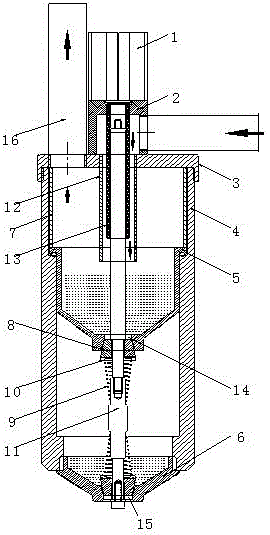
[0018] see figure 1 , in an embodiment of the present invention, a cooling liquid separation device in a vacuum processing environment, including a cylinder 1, a cylinder mounting seat 2, a tank cover 3, a tank body 4, a partition 5, a conical bottom cover 6, a spacer 7, and a sealing plug 8. Spring 9, gasket 10, two-way piston rod 11, return water conduit 12, cylinder protection tube 13, first water outlet 14, second water outlet 15 and vacuum pipe 16, the to...


PUM


Abstract

The invention discloses a coolant separation device for a vacuum processing environment. The coolant separation device comprises a cylinder, a cylinder mounting seat, a tank cover, a tank body, an interlayer, a conical sealing bottom, spacer bushes, sealing plugs, springs, a two-way piston rod, a water return guide pipe, a cylinder protecting pipe, a first water outlet, a second water outlet and a vacuum pipe. The top and the bottom of the tank body are respectively and hermetically connected with the tank cover and the conical sealing bottom. The interlayer is hermetically connected to the interior of the tank body, and divides the interior of the tank body into an upper sustaining pressure cavity and a lower buffering cavity. The tank cover presses the interlayer through the spacer bushes. The first water outlet and the second water outlet are controlled by the two-way piston rod to be opened or closed, the replacement of a coolant between the upper sustaining pressure cavity and the lower buffering cavity is realized, the internal pressure can be kept stable, the sealing performance can be ensured through the sealing structures that the water outlets are sealed by the sealing plugs, and scaling is avoided. The coolant separation device can ensure recycling of the coolant, and the operating efficiency of the coolant separation device is improved.

Description

technical field [0001] The invention relates to a cooling liquid separation device, in particular to a cooling liquid separation device in a vacuum processing environment. Background technique [0002] Generally, CNC engraving machines are commonly used in the processing of mobile phone screens and mobile phone mold protection sheets. For glass processing, a large amount of coolant is required to cool down the tool. Due to the short processing cycle of the single-piece workpiece in processing, the workpiece is often replaced. During the replacement process A large amount of cooling water enters the vacuum pipeline and enters the buffer tank with the work of the vacuum pump. Due to the circulation of the cooling liquid, there will be a large amount of glass powder and other residues in the buffer tank of the vacuum pump. Long-term work will scale in the buffer tank of the vacuum pump , Blocking the pipeline affects the vacuum degree. [0003] The existing double bottles are ...

Claims


Application Information

Patent Timeline
Patent Type & Authority Applications(China)
IPC IPC(8): B44B1/06B44B3/06
CPCB44B1/06B44B3/06B44B2700/12
Inventor 李凤阳
Owner SHENZHEN SHENGLIDA CNC EQUIP CO LTD
Why Eureka
Try Eureka