Evaporating pan for vacuum smelting furnace

A technology of vacuum smelting and evaporator, which is applied in the field of vacuum smelting devices, can solve the problems of high manufacturing cost, difficult processing, and inability to implement, and achieve the effects of reduced manufacturing cost, convenient manufacturing, and simple structure

Inactive Publication Date: 2016-11-09
永兴县亿翔环保科技有限公司
View PDF4 Cites 1 Cited by
  • Summary
  • Abstract
  • Description
  • Claims
  • Application Information

AI Technical Summary

Problems solved by technology

However, since the technical features of the patent document are not clearly defined, and the drawings in the description do not conform to the mechanical drawing standards, those skilled in the art cannot implement the content disclosed in the patent document.
Now on the market there is a evaporator with a structure similar to the patent drawings (such as figure 1 ), that is, there is a circle of protruding edge 1 on the bottom of the evaporator, and a circle of concave steps 2 on the inner side of the outer edge of the evaporator liquid tank. The steam outlet channel is S-shap

Method used


Image

  • Evaporating pan for vacuum smelting furnace
  • Evaporating pan for vacuum smelting furnace

Examples


Embodiment Construction

[0022] The present invention is described in detail below in conjunction with accompanying drawing and specific embodiment:

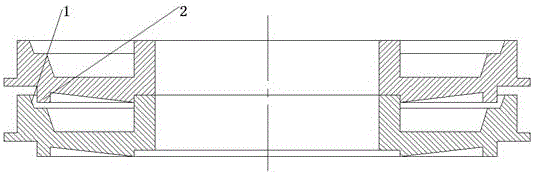
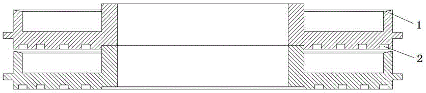
[0023] Such as figure 2 As shown, the evaporation pan for vacuum smelting furnace of the present invention is provided with at least one circle of grooves 2 on the bottom surface of the evaporation pan. The grooves 2 are arranged circularly on the bottom surface. Preferably, a circle of grooves is provided on the bottom surface of the evaporating pan corresponding to the outer edge of the liquid storage tank of the evaporating pan, so that the anti-splash effect is better. .

[0024] Four circles of grooves may be provided on the bottom surface of the evaporating tray. This works better.

[0025] The cross-sectional shape of the groove on the bottom surface of the evaporating tray is rectangular. It can also be arc-shaped.

[0026] As a further improvement, the liquid tank of the evaporator is inclined inwardly along the upper plane 1 . In this ...


PUM


Abstract

The invention discloses an evaporating pan for a vacuum smelting furnace. At least one circle of groove is formed in the bottom surface of the evaporating pan; and the upper plane of the outer edge of a liquid accommodating tank of the evaporating pan is inclined towards the inner side. According to the evaporating pan, the splashing prevention effect can be enhanced, the pollution caused by volatile matters can be relieved, and the metal recycling rate can be increased.

Description

technical field [0001] The invention relates to a vacuum smelting device, in particular to an evaporation pan used in a vacuum smelting furnace. Background technique [0002] Vacuum smelting technology originated in the 1930s and was introduced into my country in the 1950s. Due to its low energy consumption, no pollution, short process, high recovery and high efficiency, it has played an important role in the development of my country's nonferrous metallurgical industry. An internal heating continuous vacuum smelting furnace is widely used in vacuum distillation smelting such as crude metal purification and alloy separation. In the middle of this kind of vacuum smelting furnace, a plurality of disk-shaped evaporating plates are stacked to form an evaporating plate group. The evaporating plate is provided with a liquid tank for holding the metal liquid. There is a gap to form a steam outlet channel. There is a cylindrical condensation cover around the evaporator group. The e...

Claims


Application Information

Patent Timeline
IPC IPC(8): C22B9/02B01D3/00B01D3/10
CPCB01D3/00B01D3/10C22B9/02Y02P10/20
Inventor 蓝川华黄存文
Owner 永兴县亿翔环保科技有限公司
Why Eureka
Try Eureka