Prefabricated underground silo compound shaft construction method and silo structure

A prefabricated, underground silo technology, applied in underwater structures, infrastructure engineering, artificial islands, etc., can solve the problem that the force of the boot foot cannot meet the requirements, is not conducive to the layout of the building complex, and the boot foot of the caisson is not specified, etc. problems, to achieve the effect of increasing the scope and effectiveness, saving the construction period, and reducing the construction work surface

Active Publication Date: 2016-11-09
黄竟强
View PDF6 Cites 10 Cited by
  • Summary
  • Abstract
  • Description
  • Claims
  • Application Information

AI Technical Summary

Problems solved by technology

2) The method described in the literature does not explain how to solve the subsidence problem of caisson permafrost excavation, and the construction speed is slow and difficult
3) The pipe jacking receiving shaft mentioned in the literature has a circular cross-section and occupies a large area, which is not conducive to the layout in the building complex
4) The method described in the literature does not explain the caisson boots. When the caisson section is large and the excavation depth is deep, the force on the boots cannot meet the requirements
5) The structure of the literature receiving shaft adopts the ordinary caisson structure, which needs to be fabricated on site, and the construction speed is slow and the floor area is large
6) The freezing method described in the literature is independent of the caisson construction process, and the advantages of the two cannot be fully utilized to make up for the shortcomings, and the cost is relatively high
7) The method described in the literature does not seal the bottom of the well during the construction project. If the groundwater pressure is high, it is easy to cause piping accidents

Method used


Image

  • Prefabricated underground silo compound shaft construction method and silo structure
  • Prefabricated underground silo compound shaft construction method and silo structure
  • Prefabricated underground silo compound shaft construction method and silo structure

Examples


Embodiment Construction

[0036] The present invention will be further described below in conjunction with the accompanying drawings.

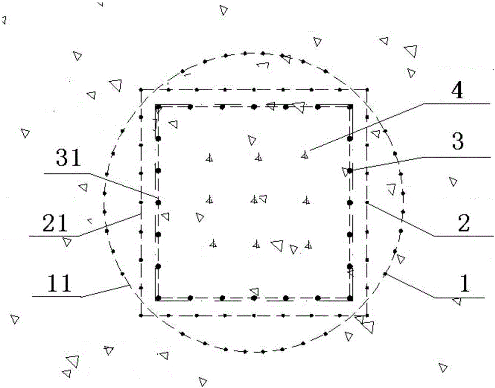
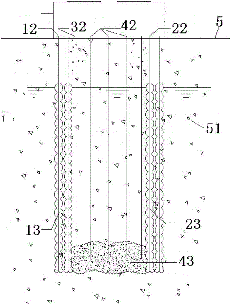
[0037] Such as Figure 1 to Figure 10 The shown prefabricated underground silo compound shaft construction method includes the following steps: a. Firstly, laying out lines at the silo construction site to locate and arrange boreholes, wherein the setting out lines are respectively: along the arched hole layout line 11 Arrange the arch ring freezing holes 1, arrange the rectangular ring freezing holes 2 along the rectangular hole layout line 21, arrange the sinking grouting holes 3 along the shaft wall layout hole line 31, the arch hole layout line 11, the rectangular hole layout line 21 and the well wall hole layout line 31 are arranged sequentially from outside to inside with reference to the excavation range line, and the survey grouting hole 4 is arranged in the well wall hole layout line 31; b, through the above-mentioned arch ring freezing hole 1 and rectangular ...


PUM


Abstract

The invention relates to the field of underground silo facilities, in particular to a prefabricated underground silo compound shaft construction method and a silo structure which effectively improve the underground silo construction efficiency and greatly reduce the construction cost. The prefabricated underground silo compound shaft construction method comprises the following steps that a, paying off is firstly carried out in a silo building site to locate and arrange drill holes; b, freezing operation and bottom grouting are carried out; c, splicing assembly is carried out to form shaft structures; d, shoe leg heating pipes in shoe leg structures are used for hydrothermal circulation; e, structure shaft components are assembled step by step to form new shaft structures till the preset depth is achieved; f, bottom plates and supporting plates are mounted; g, all drill hole openings in the ground are closed; and h, debugging and running are completed, and construction is finally completed. The prefabricated underground silo compound shaft construction method and the silo structure are high in construction reliability and construction speed and especially suitable for being used in fields with the short construction period and limited construction space.

Description

technical field [0001] The invention relates to the field of underground silo facilities, in particular to a prefabricated underground silo compound shaft construction method and a silo structure. Background technique [0002] With the continuous acceleration of my country's urbanization process, urban land resources are becoming more and more scarce. By using underground space, it is possible to achieve more efficient space exchange for land, and at the same time improve the contribution of urban infrastructure and living service facilities. The all-round and three-dimensional development of the city is conducive to protecting the ecological environment and saving natural resources, and is a reasonable and effective way for the sustainable development of the city. [0003] In the era of e-commerce, the future of cargo storage is widely optimistic, and underground storage space is a scarce resource in storage. The sealing and thermal stability of the underground space are v...

Claims


Application Information

Patent Timeline
Patent Type & Authority Applications(China)
IPC IPC(8): E02D29/05E02D3/115
CPCE02D3/115E02D29/05
Inventor 黄竟强陈静胡秉偃刘雨董世海彭丹
Owner 黄竟强
Why Eureka
Try Eureka