Floating type small pumping station

A floating pumping station technology, which is applied to pumping stations, motor vehicles, ships, etc., can solve the problems of long construction period, unstable operating conditions, and inconvenient maintenance of pumping stations, and achieve low requirements for water-stop materials and structural Simple, waterproof structure simple effect

Pending Publication Date: 2016-11-09
SHANGHAI NUOSHAN ENG DESIGN CONSULTING
View PDF0 Cites 10 Cited by
  • Summary
  • Abstract
  • Description
  • Claims
  • Application Information

AI Technical Summary

Problems solved by technology

[0007] The purpose of the present invention is to overcome the defects of long construction period, high cost, complicated structure, unstable operation condition and inconvenient maintenance of the pumping station in the prior art, and provide a small pumping station with simple structure, convenient construction and stable operation structure

Method used


Image

  • Floating type small pumping station
  • Floating type small pumping station

Examples


Embodiment 1

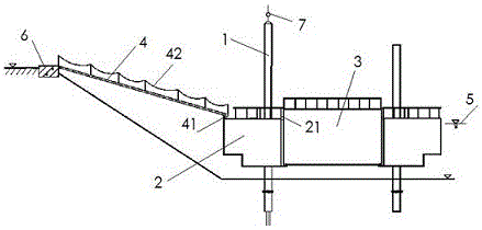
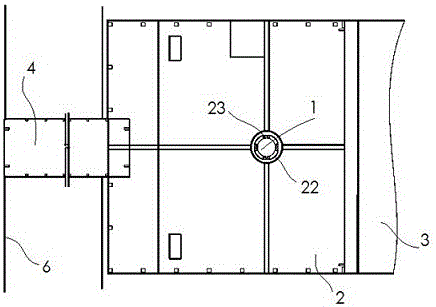
[0030] Floating small pump station, the composition of the pump station includes pile shaft 1, buoy 2, pump room 3 and traffic bridge 4; pile shaft 1 is vertically fixed in a water area suitable for water intake, buoy 2 and pump room 3 are prefabricated with reinforced concrete The empty box type overall structure. The buoy 2 and the pump chamber 3 are connected by a simply supported hinge 21, which is a socket type, and its function is a rotatable connection. Half of the hinge is a plug with a bolt hole, and the other half is a plug with a bolt hole. Concave groove, after inserting the plug into the concave groove, pass the bolt through the bolt hole and tighten the nut to form a simply supported hinge. The size and quantity of simply supported hinges are determined by calculation, and two are used in this embodiment, arranged symmetrically. The buoy 2 is provided with an inner cylinder 22 as a guide hole, and the inner cylinder is slidably matched with the pile shaft 1, and...

Embodiment 2

[0034]The bottom of the buoy 2 is an empty box with a stepped structure, and its structural size is determined by the size of the required primary buoyancy and secondary buoyancy; the primary buoyancy is determined by the total weight of the buoy 2 and the pump chamber 3, according to the minimum water absorption of the pump. The depth is determined by calculation; the second-level buoyancy is determined based on the calculation of the first-level buoyancy, plus the axial force when the water pump is working. All the other structures are with embodiment 1.


PUM


Abstract

The invention discloses a floating type small pumping station. The floating type small pumping station overcomes the defects of existing pumping stations that construction period is long, manufacturing cost is high, structure is complicated, operation condition is unstable and maintenance is inconvenient. The pumping station is composed of a pile shaft, a pontoon, a pump chamber and a traffic bridge, wherein the pile shaft is vertically fixed to a water area suitable for water sampling, the pump chamber is connected with the pontoon, and the pontoon is provided with an inner cylinder serving as a guiding hole; the inner cylinder is in sliding fit with the pile shaft, and the pontoon can move up and down along the pile shaft along with the water level change of the water area; a water pump is fixed in the pump chamber and provided with a water inlet component and a water outlet component in a matched mode, a suction port of the water pump extends to water at the bottom of the pump chamber through the water inlet component, and an output port of the water pump is connected with a water delivery pipeline on the shore through the water outlet component; the traffic bridge is of a beam and slab structure, one end of the traffic bridge is hinged to a shoreside concrete base, the other end of the traffic bridge is connected with an idler wheel through a bearing, the idler wheel can roll along the upper surface of the pontoon, and traffic between the pump chamber and the shoreside can be maintained for any water level.

Description

technical field [0001] The invention belongs to the technology of water delivery pumping stations, and in particular relates to the structure of a floating pumping station. Background technique [0002] In urban and rural production and domestic water, drainage or irrigation, the traditional method is to build fixed pumping stations, especially small pumping stations. But even if a small fixed pumping station is built, there are still many shortcomings such as complex building structure, high engineering cost and long construction period. [0003] The foundation construction of the fixed pump station and the construction of the cross-strait connection section are relatively difficult, especially in soft soil areas, the foundation construction is even more difficult. As for the built river revetment, it still needs to be dismantled and rebuilt, and the waste of repeated demolition and construction is huge. [0004] The civil construction of the fixed pumping station needs t...

Claims


Application Information

Patent Timeline
Patent Type & Authority Applications(China)
IPC IPC(8): E03B5/00B63B35/00
CPCE03B5/00B63B35/00
Inventor 朱博华唐金忠彭灿邱峰
Owner SHANGHAI NUOSHAN ENG DESIGN CONSULTING
Why Eureka
Try Eureka