Low-profile full-waveband WLAN-MIMO indoor distributed antenna

A distributed antenna, full-band technology, applied in the field of MIMO antenna, can solve the problem of lack of antenna design, and achieve the effect of reducing design time, large channel capacity, and widening frequency band

Inactive Publication Date: 2016-11-09
BEIHANG UNIV
View PDF4 Cites 4 Cited by
  • Summary
  • Abstract
  • Description
  • Claims
  • Application Information

AI Technical Summary

Problems solved by technology

At present, there are few research reports on multi-mode indoor an

Method used


Image

  • Low-profile full-waveband WLAN-MIMO indoor distributed antenna
  • Low-profile full-waveband WLAN-MIMO indoor distributed antenna
  • Low-profile full-waveband WLAN-MIMO indoor distributed antenna

Examples


Embodiment 1

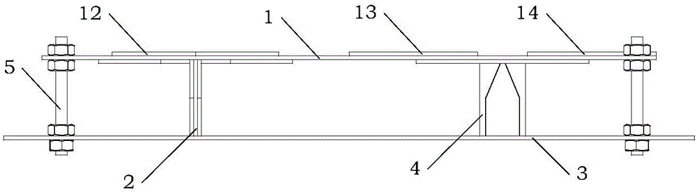
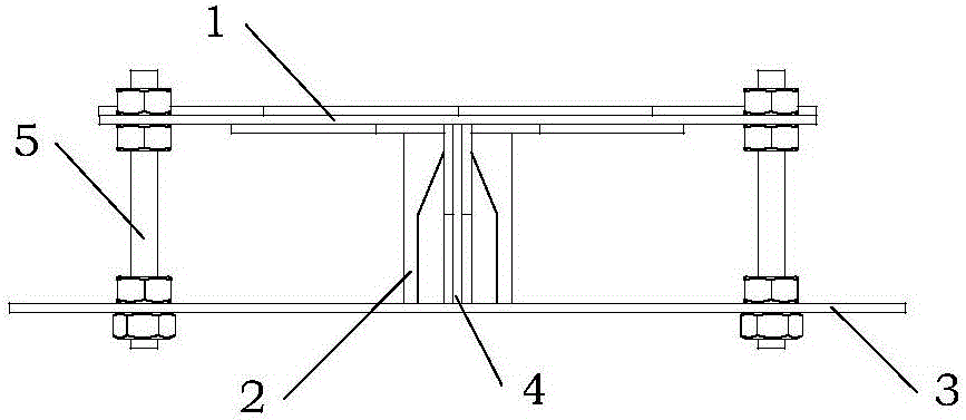
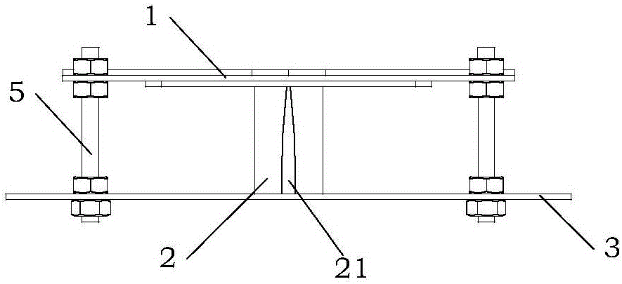
[0091] In order to verify as figure 1 , Figure 1C , Figure 1D In the design shown, there are at least two low-profile full-band WLAN-MIMO indoor distributed antennas with at least two radiating bodies arranged in an orthogonal distribution. The specific dimensions of the antenna are set as:

[0092] The length E=160mm of the first transverse dielectric plate 1, the width D=100mm of the first transverse dielectric plate 1;

[0093] The distance between the radiation center points U=80mm;

[0094] The distance between the first transverse dielectric plate 1 and the first reflection plate 3 is 20mm;

[0095] The major radius R of the back bar 长 = 32mm, the short radius R of the back bar 短 =15.2mm, copper clad width R of the back strip a =8mm, the distance R between two back strips b =13mm;

[0096] The radius R of the semicircle in the vibrator configuration is 14mm, the upper base width of the trapezoid in the vibrator configuration is w=1.9mm, the height of the trapez...

Embodiment 2

[0144] In order to verify as Figure 6 , Figure 6C In the design shown, there are at least three radiating bodies arranged according to the circumference of the low-profile full-band WLAN-MIMO indoor distributed antenna. The specific size of the antenna is set as:

[0145] The length E=160mm of the second transverse medium plate 10, the width D=160mm of the second transverse medium plate 10;

[0146] The distance between the radiation center points U=80mm;

[0147] The distance between the second transverse dielectric plate 10 and the second reflection plate 30 is 20 mm;

[0148] The major radius R of the back bar 长 = 32mm, the short radius R of the back bar 短 =15.2mm, the copper clad width R of the back strip a =8mm, the distance R between two back strips b =13mm;

[0149]The radius R of the semicircle in the vibrator configuration is 14mm, the upper base width of the trapezoid in the vibrator configuration is w=1.9mm, the height of the trapezoid in the radius vibrato...


PUM

PropertyMeasurementUnit
Reflection coefficientaaaaaaaaaa

Abstract

The invention discloses a low-profile full-waveband WLAN-MIMO indoor distributed antenna with an orthogonal or circumferential distribution radiation body. The antenna is composed of a transverse dielectric plate, a longitudinal dielectric plate, a reflecting plate, a Balun, back strips and a vibrator, wherein the back strips and the vibrator are manufactured by adopting the copper coating technology. The antenna is in the form of a MIMO antenna capable of covering the full WLAN frequency band. According to the technical scheme of the invention, the relative positions of the back strips relative to the vibrator are changed. Meanwhile, the back strips are coupled to the vibrator to generate the inductive capacitance so as to adjust the performances of an ultra-wideband antenna, such as working waveband, antenna gain, antenna directionality and the like. Through adjusting the distance and the angle between antenna units, the antenna is minimized, high in isolation degree, low in correlation coefficient and high in gain. The antenna covers all wide frequency bands during the current wireless communication process and is large in data capacity.

Description

technical field [0001] The present invention relates to a MIMO antenna suitable for indoor use, more particularly, to a low-profile full-band WLAN-MIMO indoor distributed antenna with an orthogonally distributed radiation body or a circumferentially distributed radiation body. Background technique [0002] In order to improve the throughput, transmission distance and reliability of WLAN (Wireless Local Area Network), the new generation of wireless local area network standard 802.11n introduces MIMO (Multiple-Input Multiple-Out) technology, and WLAN MIMO system The realization of MIMO not only depends on the design of the MIMO radio frequency module, but also depends on the development of the base station MIMO antenna responsible for the upload and download functions. Its performance directly affects the overall performance of the entire WLAN MIMO system. Therefore, the popularization and application of WLAN MIMO system puts forward two basic requirements for the development ...

Claims


Application Information

Patent Timeline
IPC IPC(8): H01Q1/36H01Q1/38H01Q19/10H01Q15/14H01Q1/52H01Q3/00H01Q5/10
CPCH01Q1/36H01Q1/38H01Q1/52H01Q3/00H01Q5/10H01Q15/14H01Q19/10
Inventor 吴琦郭双苏东林
Owner BEIHANG UNIV
Why Eureka
Try Eureka