
Low coupling ultra-wide band MIMO antenna

An ultra-wideband, low-coupling technology, applied in the field of ultra-wideband antennas, can solve the problems of reducing antenna unit isolation, low coupling, and low coupling, and achieve the effects of improving isolation, low price, and low production cost

Inactive Publication Date: 2016-11-09
NORTHWESTERN POLYTECHNICAL UNIV
View PDF4 Cites 8 Cited by
  • Summary
  • Abstract
  • Description
  • Claims
  • Application Information

AI Technical Summary

Problems solved by technology

In order for a MIMO system to have good performance, the antenna elements in the transmitter or receiver are uncorrelated (low coupling), however, it is still a comparison to integrate multiple broadband antennas in portable devices with low coupling. tricky question
[0003] In recent years, some technologies have been proposed to reduce the isolation between antenna elements in UWB MIMO systems. For example, different forms of parasitic structures can be loaded on the back of printed monopoles to achieve ultra-wideband decoupling. The isolation in the ultra-wide frequency band can be improved by loading double-layer EBG (electromagnetic band-gap). The middle line technology is considered to be one of the more promising decoupling technologies because it requires a smaller size and does not need to be placed on the floor. corrections, however, this technique typically only achieves decoupling in a narrow band

Method used

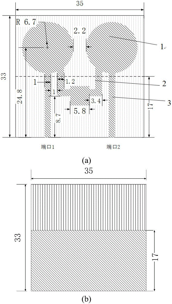
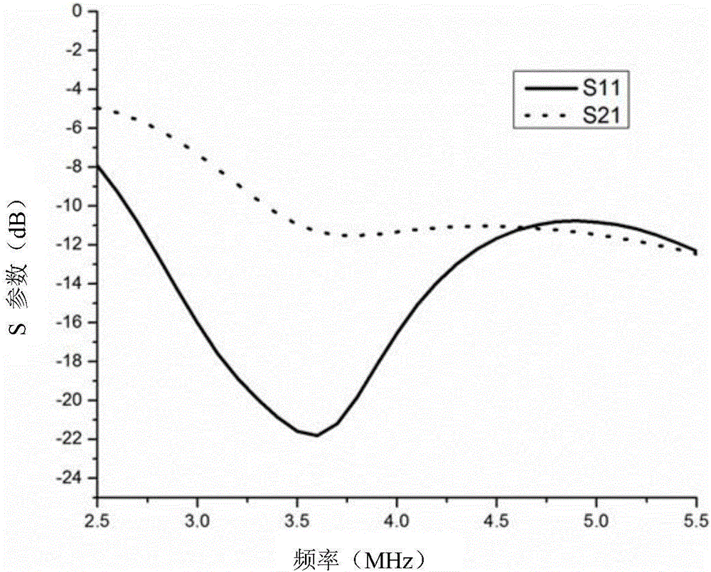
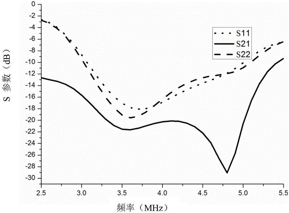

Image

  • Low coupling ultra-wide band MIMO antenna
  • Low coupling ultra-wide band MIMO antenna
  • Low coupling ultra-wide band MIMO antenna

Examples


Embodiment Construction

[0014] The present invention will be further described below in conjunction with the accompanying drawings and embodiments.

[0015] In order to solve the coupling problem of the ultra-wideband MIMO antenna system and reduce the correlation between the antenna units, we need to load a certain decoupling structure to improve the coupling degree between the antenna units of the MIMO system.

[0016] The low-coupling ultra-wideband MIMO antenna designed by the present invention consists of two circular printed monopole radiation patches with the same size and ultra-wideband radiation characteristics, an intermediate line structure, a rectangular parallelepiped dielectric plate, a 50-ohm microstrip line, and a floor and 50 ohm SMA connectors.

[0017] The middle line structure is as follows: the middle is a square patch, and a metal arm extends from the left and right sides of the square patch to connect with the circular printed monopole radiation patch, and the middle line struc...


PUM


Abstract

The invention provides a low coupling ultra-wide band MIMO antenna and relates to the field of MIMO antennas. the structure of a common neutralizing wire is deformed so as to achieve de-coupling inside an ultra-wide band. The structure of the neutralizing wire has a square patch in the middle thereof. The two edges of the square patch are parallel to a microstrip line and separately extend a L-shaped metal arm which is connected to a circular printing monopole radiation patch. According to the invention, since the de-coupling structure is arranged between two antenna units, the size of the whole MIMO is smaller; the adding of the de-coupling structure effectively increases isolation of the frequency band; the circular printing monopole radiation patch, the deformed structure of the neutralizing wire and the 50 ohm microstrip line all adopt the printing structure; a medium substrate uses FR4 having a 4.4 dielectric constant, and the FR4 as the most common material for a PCB plate is cheap and easy to purpose. Therefore, according to the invention, the antenna has low manufacturing cost, is easy to process, can be manufactured on a large scale, and has greater practical application value.

Description

technical field [0001] The invention relates to the field of MIMO antennas, in particular to ultra-wideband antennas. Background technique [0002] With the rapid development of wireless communication technology, people are more and more dependent on wireless terminals, and with the development of wireless communication technology, the demand for high quality and high data transmission rate has increased. Multiple-input multiple-output technology is considered to be the most promising to achieve this goal. The feature of MIMO is to have multiple antennas in the transmitter or receiver, and to use multipath properties to improve transmission quality and system capacity. In order for a MIMO system to have good performance, the antenna elements in the transmitter or receiver are uncorrelated (low coupling), however, it is still a comparison to integrate multiple broadband antennas in portable devices with low coupling. tough question. [0003] In recent years, some technologi...

Claims


Application Information

Patent Timeline
Patent Type & Authority Applications(China)
IPC IPC(8): H01Q1/52H01Q1/38H01Q21/00H01Q1/48
CPCH01Q1/52H01Q1/38H01Q1/48H01Q1/521H01Q1/523H01Q21/00
Inventor 郭陈江江磊丁君
Owner NORTHWESTERN POLYTECHNICAL UNIV
Learn More