
Electric arc correcting system and electric arc correcting device thereof

A technology of arc and arc torch, which is applied in the direction of auxiliary equipment, auxiliary welding equipment, welding/cutting auxiliary equipment, etc. It can solve the problems of slowing down the swing speed, increasing the process, reducing work efficiency, etc., and achieves stable arc voltage and light overall structure , The effect of convenient energy adjustment

Active Publication Date: 2016-11-16
CSSC HUANGPU WENCHONG SHIPBUILDING COMPANY
View PDF6 Cites 0 Cited by
  • Summary
  • Abstract
  • Description
  • Claims
  • Application Information

AI Technical Summary

Problems solved by technology

[0004] (1) Hand-held operation by skilled professional technicians is required to correct the deformation of aluminum alloy at close range for a long time, and the arc radiation and aluminum dust pollution brought about will have adverse effects on health
[0005] (2) Due to the constant changes in the height and angle between the welding torch and the surface of the aluminum alloy during manual arc correction, the heat input from the arc to the surface of the aluminum alloy is unstable, resulting in frequent overburning of the surface and defects such as arc craters, which damage the surface of the aluminum alloy
[0006] (3) It is necessary to perform mechanical scribing on the area to be corrected, which will damage the aluminum alloy surface, and the manual swing cannot accurately reach the scribing place. In order to get as close to the scribing place as possible, the swing speed will be slowed down, resulting in the residence time at the two ends of the swing path Defects such as long, arc craters caused by overburning, etc. need to be filled twice, increasing the process and reducing work efficiency
[0007] (4) It is difficult to control the swing speed and forward speed during manual operation, let alone adopt a faster speed at the swing end

Method used


Image

  • Electric arc correcting system and electric arc correcting device thereof
  • Electric arc correcting system and electric arc correcting device thereof
  • Electric arc correcting system and electric arc correcting device thereof

Examples


Embodiment Construction

[0043] Embodiments of the present invention will now be described with reference to the drawings, in which like reference numerals represent like elements.

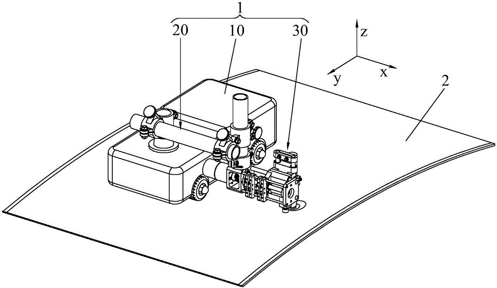
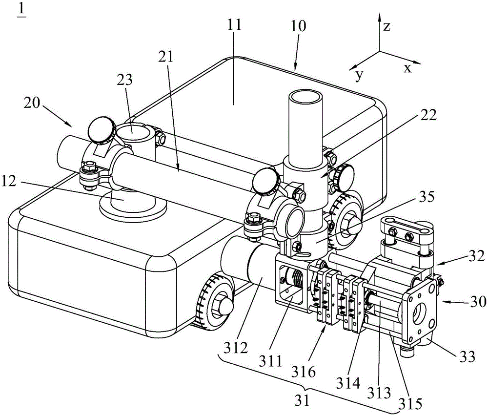
[0044] see first figure 1 As shown, the arc straightening system of the present invention includes an arc straightening device 1 and a part 2 to be straightened after welding. Wherein, the part 2 to be corrected is a welded hull aluminum alloy thin plate, which has a curved surface structure, but is not limited thereto. The arc straightening device 1 is a non-melting inert gas tungsten shielded welding (TIG) arc straightening device, the arc swing speed can be controlled in sections, the swing amplitude is constant, the distance between the arc and the surface of the workpiece 2 to be straightened is constant, and it can run automatically , so it is especially suitable for correcting the welding deformation of aluminum alloy thin-walled hulls. On the basis of ensuring the surface quality of the hull, it can correct the c...


PUM


Abstract

The invention discloses an electric arc correcting device. The electric arc correcting device comprises a correcting mechanism, a walking mechanism and a control module. The correcting mechanism comprises an electric arc gun, a height control assembly and a transverse control assembly, wherein the height control assembly and the transverse control assembly are connected with the electric arc gun. The height control assembly can generate displacement in the vertical direction along with the shape of a workpiece to be corrected, and the transverse control assembly can control the transverse displacement of the electric arc gun. The walking mechanism is used for bearing the correcting mechanism. The control module is electrically connected with the correcting mechanism and the walking mechanism and used for controlling running of the correcting mechanism and the walking mechanism. The swinging speed of the electric arc correcting device is adjustable, the swinging amplitude of the electric arc correcting device is constant, the distance between the electric arc correcting device and the surface of the workpiece to be corrected is constant, and the electric arc correcting device can automatically walk. The invention further discloses an electric arc correcting system with the electric arc correcting device.

Description

technical field [0001] The invention relates to the technical field of ship welding correction, in particular to an arc correction system and an arc correction device for non-melting inert gas tungsten shielded welding (TIG) with adjustable swing speed. Background technique [0002] During the construction of the hull structure of an aluminum ship, aluminum alloy sheets are prone to welding deformation during assembly and welding, resulting in uneven hull surfaces. If the deformation is not corrected, it will affect the assembly deviation of the hull components and affect the ship. Construction, and will reduce the surface smoothness of the hull and increase the sailing resistance. Therefore, appropriate technological measures must be taken to correct post-weld deformation. [0003] The traditional "water-fire method" is heating with the help of an open flame generated by oxyacetylene, followed by rapid cooling with cold water, so that the convex surface shrinks and deforms...

Claims


Application Information

Patent Timeline
Patent Type & Authority Applications(China)
IPC IPC(8): B23K31/00B23K37/02
Inventor 闫德俊蒋佳霖王旭王洪波谢浩黎书华钟美达罗玖强王毅陈忠前曾宁杰王勇田鹏
Owner CSSC HUANGPU WENCHONG SHIPBUILDING COMPANY
Learn More