Spiral spindle for lens vacuum coating machine

A technology of vacuum coating machine and spiral spindle, which is applied in the direction of vacuum evaporation coating, shaft, mechanical equipment, etc., and can solve the problems that air tightness cannot be guaranteed

Active Publication Date: 2016-11-16
JIANGSU RARE OPTICS CO LTD
View PDF6 Cites 0 Cited by
  • Summary
  • Abstract
  • Description
  • Claims
  • Application Information

AI Technical Summary

Problems solved by technology

When the main shaft rotates, it needs to reciprocate due to technological requirements. If an ordinary main shaft is used, there will be a gap at the end during the reciprocating movement, so the airtightness cannot be guaranteed.

Method used


Image

  • Spiral spindle for lens vacuum coating machine

Examples


Embodiment Construction

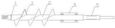
[0009] Depend on figure 1 It is known that a spiral spindle for a lens vacuum coating machine is composed of a V-shaped shaft end 1, a shaft body 2, a spiral blade 3, a sealing sleeve 4, and a keyway 5; At one end, the spiral blade 3 has a rotation pitch of 200 mm and is welded on the shaft body 2. The sealing sleeve 4 is set on the other end of the shaft body 2. The keyway 5 is processed on the stressed end of the shaft body 2. One on the opposite side; when the shaft body 2 is in use, a spring and a V-shaped cone are installed on the machine tool facing the port of the V-shaped shaft end 1, and the V-shaped cone and the port of the V-shaped shaft end 1 are matched. 2. When the reciprocating motion occurs, the spring always bears against the V-shaped cone, and the V-shaped cone and the V-shaped shaft end 1 port are always in a state of precise cooperation, thus ensuring that the shaft body 2 will not leak air when the shaft body 2 performs reciprocating operation; The inside...


PUM


Abstract

A spiral spindle for a lens vacuum coating machine is composed of a V-shaped spindle end (1), a spindle body (2), a spiral blade (3), a sealing spindle sleeve (4) and key grooves (5). The sealing spindle sleeve (4) and the spiral blade (3) are arranged on the spindle body (2). One end of the spindle body (2) is the V-shaped spindle end (1), and the other end of the spindle body (2) is provided with the sealing spindle sleeve (4). The spiral spindle for the lens vacuum coating machine is characterized in that the spiral blade (3) is welded to the spindle body (2), and the key grooves (5) are formed in the stress surface of one side of the spindle body (2) and are symmetrically arranged; and a spring and a V-shaped cone are installed at a port of the V-shaped spindle end (1), and the V-shaped cone is in close fit with the V-shaped spindle end (1). According to the spiral spindle for the lens vacuum coating machine, multiple layers of sealing rings are designed inside the spindle sleeve, so that the effect that no gas leakage occurs between the spindle body and the sealing spindle sleeve is guaranteed, and under the dual guarantee of the port of the V-shaped spindle end and the sealing spindle sleeve, the spindle body ensures that the situation that vacuum gas escapes out of the coating machine from the matching surface of the spindle due to non-tight sealing is avoided.

Description

technical field [0001] The invention relates to a helical main shaft, which is especially suitable for the helical main shaft used in a lens vacuum coating machine. Background technique [0002] The lens vacuum coating machine needs to pump out the air inside the body when it is in use. The known coating machine directly connects the air pump to the coating machine. Vibration occurs. Moreover, the coating machine will generate high heat when the coating machine coats the lens. If the air is pumped sharply inside the body, more thermal ions will accumulate in the body. It is difficult to remove them after the vacuum degree reaches a certain value. Pull out the coating machine body. In order to ensure the extraction of thermions during the entire vacuum pumping process, the cooperation of the entire spindle is required and airtightness must be ensured to ensure that the vacuum gas will not escape from the coating machine from the mating surface of the spindle due to poor sea...

Claims


Application Information

Patent Timeline
Patent Type & Authority Applications(China)
IPC IPC(8): C23C14/00F16C3/02F16J15/16
CPCC23C14/00F16C3/02F16C2361/31F16J15/16
Inventor 包松养
Owner JIANGSU RARE OPTICS CO LTD
Why Eureka
Try Eureka