Accurate multi-point real-time temperature measurement method and system for permanent magnet synchronous motor

A permanent magnet synchronous motor, precise technology, applied in the direction of thermometers, thermometers, measuring heat, etc., which use electrical/magnetic components directly sensitive to heat, and can solve problems affecting measurement accuracy and real-time performance.

Active Publication Date: 2019-03-29
嘉兴彬澄物联科技有限公司
View PDF5 Cites 0 Cited by
  • Summary
  • Abstract
  • Description
  • Claims
  • Application Information

AI Technical Summary

Problems solved by technology

[0005] The purpose of the present invention is to solve the problem of measuring the internal temperature of the motor with a two-wire bare-mounted temperature sensor, which will seriously affect the measurement accuracy and real-time performance due to strong electromagnetic interference, and provides a precise multi-point real-time temperature measurement method for permanent magnet synchronous motors and system

Method used


Image

  • Accurate multi-point real-time temperature measurement method and system for permanent magnet synchronous motor
  • Accurate multi-point real-time temperature measurement method and system for permanent magnet synchronous motor
  • Accurate multi-point real-time temperature measurement method and system for permanent magnet synchronous motor

Examples


Embodiment 1

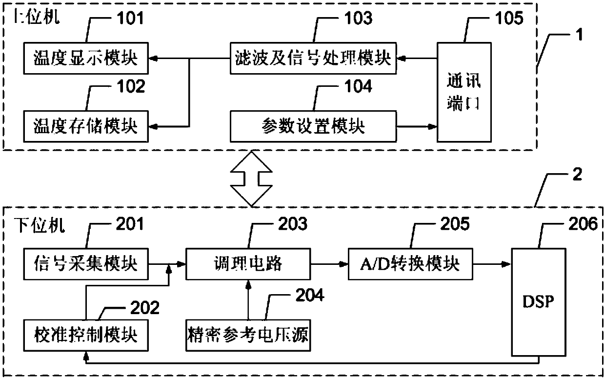
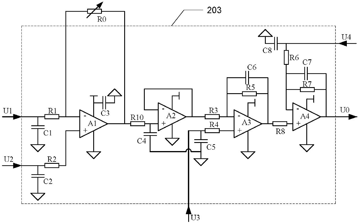
[0065] see figure 1 It is an accurate multi-point real-time temperature measurement system for permanent magnet synchronous motors. It includes a host computer 1 and a lower computer 2. The temperature signal is collected in real time through a temperature sensor. After the resistance signal is converted into a voltage signal by the conditioning circuit 203, the A / The D conversion module 205 processes it into a digital signal that can be recognized by the digital system, and the lower computer processor DSP206 completes tasks such as signal sampling, calibration circuit control, and data transmission. The upper computer 1 mainly performs parameter setting, filtering and signal processing, and performs real-time display and data storage of the obtained temperature signal. The upper computer 1 and the lower computer 2 communicate in real time through the communication bus.

[0066] When the motor is not started, the measurement system is connected, and the DSP206 controls the ...

Embodiment 2

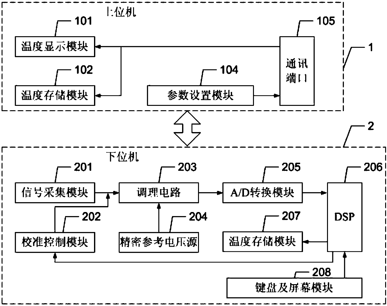
[0076] Embodiment 2: The measurement system given in this embodiment is not much different from Embodiment 1. On the basis of Embodiment 1, a keyboard and a screen module 208 are added to the lower computer 2 to undertake the work of system parameter setting and temperature signal real-time display respectively. . In this system, the lower computer processor DSP206 mainly completes tasks such as calibration circuit control, filtering, signal processing, and temperature display. The upper computer 1 can complete tasks such as parameter setting and temperature data storage through the communication port as required, and the temperature data can also be stored in the memory card of the lower computer 2 or the hard disk of the upper computer 1 .


PUM


Abstract

The invention discloses an exact multi-point real-time temperature measurement method and system for a permanent magnet synchronous motor, and belongs to the field of permanent magnet synchronous motors. The method and the system solve the problem that the measurement accuracy and the instantaneity are seriously influenced by strong electromagnetic interference when the internal temperature of the motor is measured by adopting a two-wire system nude temperature sensor. The method comprises the following steps: step 1, when the motor is not started, calibrating the measurement parameter of each temperature measurement point in sequence, acquiring actual offset b' and actual gain k' in a linear relation between input resistance signals and output voltage signals and lead resistance FORMULA at each measurement point, and acquiring a calibrated linear relation FORMULA between input resistance signals and output voltage signals; and step 2, starting the motor to work, acquiring, by a lower computer control unit, the output voltage signals of all measurement points in sequence according to the calibrated relation, digitally filtering, by an upper computer, the series of data to remove interference signals, and thus acquiring an exact temperature value of each measurement point on the motor.

Description

technical field [0001] The invention belongs to the field of permanent magnet synchronous motors. Background technique [0002] Permanent magnet synchronous motors are becoming more and more widely used in electric vehicles. In the design process of the permanent magnet synchronous motor, it is necessary to conduct temperature rise experiments on the motor. Through the observation and analysis of the temperature change during the operation of the motor, the heat dissipation performance of the motor can be judged to ensure the reliability of the motor operation. Especially in some occasions with special temperature conditions, it is necessary to ensure that the motor operates at a safe temperature before the motor can work normally. [0003] At present, for a motor with a complex structure, due to its small heat dissipation space, higher requirements are placed on the cooling of the motor, and the temperature of the motor needs to be monitored accurately in real time, which ...

Claims


Application Information

Patent Timeline
Patent Type & Authority Patents(China)
IPC IPC(8): G01K7/18
CPCG01K7/18
Inventor 佟诚德苑子航陈敬东郑萍赵白鸽
Owner 嘉兴彬澄物联科技有限公司
Why Eureka
Try Eureka