Optical micro-cavity, force measuring device and method, modulus measuring method and display panel

An optical microcavity and measuring device technology, applied in the field of force measurement, can solve the problems of complex design and manufacturing process, cannot be fundamentally eliminated, and high cost, and achieve the effects of easy batch production, simple structure, and improved efficiency

Active Publication Date: 2016-11-16
BOE TECH GRP CO LTD +1
View PDF5 Cites 11 Cited by
  • Summary
  • Abstract
  • Description
  • Claims
  • Application Information

AI Technical Summary

Problems solved by technology

[0003] In the mechanical linkage force measurement device, the contact damping between the mechanical components cannot be avoided, which inevitably introduces additional system errors
In the electronic linkage force measuring device, it is impossible to fundamentally eliminate the influence of external factors such as electromagnetic environment, humidity, temperature, etc. on the measurement, resulting in errors
The optical fiber sensor linkage type force measurement device has good anti-interference ability and measurement accuracy, but the optical design requires high precision, and the design and production process is complicated and the cost is high

Method used


Image

  • Optical micro-cavity, force measuring device and method, modulus measuring method and display panel
  • Optical micro-cavity, force measuring device and method, modulus measuring method and display panel
  • Optical micro-cavity, force measuring device and method, modulus measuring method and display panel

Examples


Embodiment Construction

[0037]In order to make the technical problems, technical solutions and advantages to be solved by the embodiments of the present invention clearer, the technical solutions of the embodiments of the present invention will be clearly and completely described below in conjunction with the accompanying drawings. Apparently, the described embodiments are some, not all, embodiments of the present invention. Based on the described embodiments of the present invention, all other embodiments obtained by those skilled in the art without creative efforts also fall within the protection scope of the present invention.

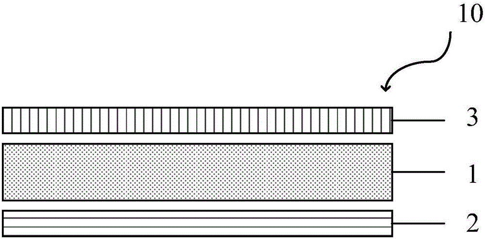
[0038] figure 1 is a schematic structural view of the optical microcavity provided according to the first embodiment of the present invention. An embodiment of the present invention provides an optical microcavity 10, comprising: a photoluminescent layer 1 configured to generate light. Photonic crystal layer 2 , provided on one side of photoluminescent layer 1 , is confi...


PUM

PropertyMeasurementUnit
thicknessaaaaaaaaaa
thicknessaaaaaaaaaa
refractive indexaaaaaaaaaa

Abstract

An embodiment of the invention provides an optical micro-cavity, a force measuring device, a force measuring method, a modulus measuring method and a display panel. The optical micro-cavity comprises a photoluminescence layer, a photonic crystal layer and a semi-transmitting and semi-reflecting layer, wherein the photoluminescence layer is configured to generate light; the photonic crystal layer is arranged on one side of the photoluminescence layer, and is configured to reflect the light generated by the photoluminescence layer and transmit excitation light used for the photoluminescence layer; and the semi-transmitting and semi-reflecting layer is arranged on the other side of the photoluminescence layer and opposite to the photonic crystal layer, and is configured to transmit and reflect the light generated by the photoluminescence layer partially. The force measuring device comprises the optical micro-cavity and at least one optical sensor. According to the embodiment, the optical micro-cavity, the force measuring device and the display panel provided by the invention are simple in structure and easy in batch manufacturing, and the force measuring method and the modulus measuring method provided by the invention are easy to implement.

Description

technical field [0001] The invention relates to the technical field of force measurement, in particular to an optical microcavity, a force measurement device and method, a modulus measurement method and a display panel. Background technique [0002] In the existing field of force measurement, especially in the field of micro force measurement, interlocking measurement is mainly used, including mechanical interlocking, electronic interlocking and optical fiber interlocking. The mechanical linkage force measuring device includes, for example, a spring balance, which measures the force to be measured according to the displacement of the mechanical parts under the action of the force to be measured. The electronic interlocking force measuring device includes, for example, a high-precision electronic scale, which measures the force to be measured according to the change of the characteristic value of the electronic component under the action of the force to be measured. In the o...

Claims


Application Information

Patent Timeline
Patent Type & Authority Applications(China)
IPC IPC(8): G01L1/24
CPCG01L1/241G01L1/24G01L1/247G06F3/041G06F2203/04105
Inventor 张晓晋于成生谢蒂旎
Owner BOE TECH GRP CO LTD
Why Eureka
Try Eureka