A dichotomy-based machine tool machining stability boundary rapid solving method

A stability and dichotomy technology, applied in the field of fast solution of machine tool machining stability boundary based on dichotomy, can solve problems such as difficult to meet actual engineering needs, numerical integration method calculation speed is not fast enough, calculation time is long, etc., to achieve process parameters High-speed and high-precision machining, moderate precision, and the effect of reducing calculation time

Active Publication Date: 2016-11-16
HUAZHONG UNIV OF SCI & TECH
View PDF0 Cites 4 Cited by
  • Summary
  • Abstract
  • Description
  • Claims
  • Application Information

AI Technical Summary

Problems solved by technology

However, considering that the solution of the stable domain requires a discrete parameter domain plane, the calculation speed of the numerical integration method is still not fast enough, especially when there are many discrete points in the parameter domain, the calculation time is still long, and it is difficult to meet the actual needs of the project.

Method used


Image

  • A dichotomy-based machine tool machining stability boundary rapid solving method
  • A dichotomy-based machine tool machining stability boundary rapid solving method
  • A dichotomy-based machine tool machining stability boundary rapid solving method

Examples


Embodiment 1

[0065] This embodiment is a single-degree-of-freedom system, and the milling stability is solved according to the method of the present invention, and its steps are:

[0066] (1) Set the parameter plane, the parameter plane is: the x-axis is the milling speed Ω (rpm), the upper and lower boundaries are 5000rpm-25000rpm, and the y-axis is the milling depth a p (m), the upper and lower boundaries are 0-0.008m; the function f(x) is the maximum value of the absolute value of the characteristic root of the judgment stability matrix minus 1; set the radial depth of cut a / D=0.50; set the number of iterations i=5. Other related parameters: number of milling cutter teeth N=2; tangential cutting force coefficient K t =6×10 8 (N / m 2 ); normal cutting force coefficient K n =2×10 8 (N / m 2 ); system natural frequency f n =922(Hz); relative damping ζ=0.011; model mass m t= 0.03993 (kg); in the numerical integration method, the initial discrete number n = 20; then, the entire paramete...

example 2

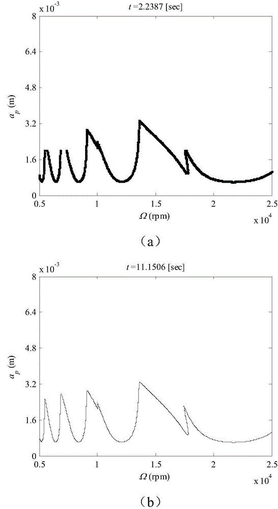
[0074] This embodiment is a two-degree-of-freedom system, and the milling stability is solved according to the method of the present invention, and its steps are:

[0075] (1) Set the parameter plane, the parameter plane is: the x-axis is the milling speed Ω (rpm), the upper and lower boundaries are 5000rpm-25000rpm; the y-axis is the milling depth a p (m), the upper and lower boundaries are 0-0.008m; the function f(x) is the maximum value of the absolute value of the characteristic root of the judgment stability matrix minus 1; set the radial depth of cut a / D=0.50; set the number of iterations i=4. Other parameters: number of milling cutter teeth N=2; tangential cutting force coefficient K t =6×10⁸(N / m 2 ); normal cutting force coefficient K n =2×10⁸(N / m 2 ); system natural frequency ω x = ω y =922(Hz); relative damping ζ x =ζ y =0.011; model mass m x = m y =0.03993(kg); the initial discrete number in the numerical integration method is n=15; then the entire paramet...


PUM


Abstract

The invention provides a dichotomy-based machine tool machining stability boundary rapid solving method comprising the steps of presetting a parameter plane, a stability judging function and the number of iterations, and performing preliminary division on the parameter plane; dividing each grid cell further into smaller sub-grid cells by using two-dimensional dichotomy; solving the function values of the stability judging function at the vertexes of each sub-grid cell by using the numerical integration method and judging whether the sub-grid cells are containing grid cells; dividing non-containing grid cells and performing judgment again, terminating the process if the obtained grid cells are still non-containing grid cells, and otherwise acquiring new containing grid cells; further dividing all the acquired containing grid cells into smaller sub-grid cells by using two-dimensional dichotomy; performing judgment and division repeatedly to gradually approach an f(x) curve until the preset number of iterations is reached; performing linear interpolation on all the finally acquired containing grid cells to obtain an approximate stability judging function null point, and drawing a scatter diagram to obtain a stability boundary. The method can effectively reduce calculation time and solve stability boundaries rapidly.

Description

technical field [0001] The invention relates to the field of machine tool processing parameter optimization and milling stability analysis, in particular to the solution of the stability boundary, and more specifically, a method for quickly solving the stability boundary of machine tool processing based on the dichotomy method. Background technique [0002] Complex free-form surface parts (such as impellers, blades, propellers, etc.) have weak stiffness due to structural features such as thin walls and cantilevers during processing. Chatter and other phenomena, which in turn cause processing defects, equipment failure and other problems, and will accelerate tool wear. Among them, machining instability refers to strong vibration due to the interaction between the tool and the workpiece during machining, which is mainly caused by resonance and chatter. Compared with machining resonance, machining chatter is unavoidable. Therefore, in order to reduce the influence of machining...

Claims


Application Information

Patent Timeline
Patent Type & Authority Applications(China)
IPC IPC(8): G06F19/00
CPCG16Z99/00
Inventor 张小俭解亚昆丁汉陈丁
Owner HUAZHONG UNIV OF SCI & TECH
Why Eureka
Try Eureka