Integrated tester for wave optics

A comprehensive testing and wave optics technology, applied in instruments, teaching models, educational appliances, etc., can solve the problems of expensive instruments, high cost, and expensive experimental instruments, and achieve the effects of low price, long life, and intuitive explanation.

Inactive Publication Date: 2016-11-16
TAIYUAN INST OF TECH
View PDF0 Cites 4 Cited by
  • Summary
  • Abstract
  • Description
  • Claims
  • Application Information

AI Technical Summary

Problems solved by technology

In early teaching, people used polarized light testing equipment to verify Malius' law and measure Brewster's angle, but the equipment was expensive
In short, in early teaching, different experimental items require different experimental instruments, and the experimental instruments are expensive and cost a lot.

Method used


Image

  • Integrated tester for wave optics

Examples


Embodiment 1

[0018] Embodiment 1——double-slit interference experiment and measurement of interference fringes:

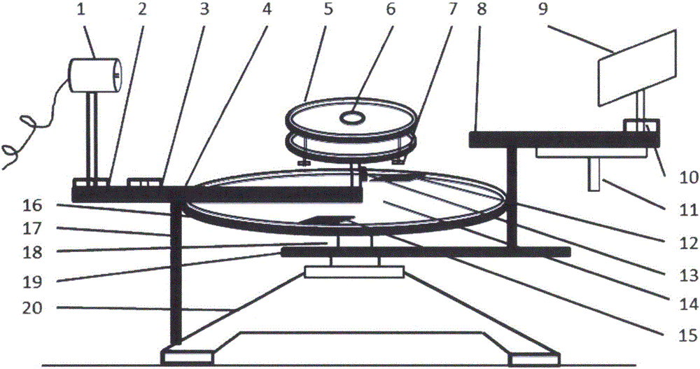
[0019] Install and fix the prepared double slits (the distance between the double slits can be 0.1mm-0.5mm) on a bracket, insert the bracket into the spare base 3, turn on the laser 1, let the laser pass through the double slits, and adjust the light screen so that The light passing through the double slits is projected onto the light screen, forming equally spaced interference fringes. Fine-tune the light screen 9 so that the center of one of the interference fringes (dark) fringes coincides with the white line in the light screen, and record the readings of α cursor 15 and β cursor 12 as α 1 and beta 1 , and then move the handle 11 to make the white line reach the center of the adjacent bright (dark) stripe, record the readings of the two verniers at this time α 2 and beta 2 , so that the angle θ of the hand wheel (light screen) movement can be calculated, that is From th...

Embodiment 2

[0020] Example 2——Single-slit diffraction experiment and measurement of central bright pattern

[0021] Install the prepared single slit (the width of the single slit is 0.1mm-0.3mm) on a bracket, insert the bracket into the spare base 3, turn on the laser 1, let the laser pass through the single slit, adjust the light screen to make the diffraction The pattern is projected onto the light screen, move the light screen 9 so that the cross hair is fixed at the center of the +1 dark pattern, and read the readings of the two cursors at this time. The readings of α cursor 15 and β cursor 12 are denoted as α 1 and beta 1 , and then turn the light screen so that the intersection of the cross on the light screen is fixed at the center of the -1 level dark fringe, and the readings of α cursor 15 and β cursor 12 at this time are denoted as α 2 and beta 2 , using the formula Calculate the rotated angle θ, and the distance L between the light screen and the single slit can be read fro...

Embodiment 3

[0022] Embodiment 3——circular hole diffraction experiment and measurement of Airy disk diameter

[0023] Install the prepared round hole (the diameter of the round hole is 0.1mm-0.5mm) on the bracket, insert it into the base 3, let the laser 1 pass through the round hole, and adjust the light screen 9 so that the light passing through the round hole is projected onto the light screen , forming a circular hole diffraction pattern. Fine-tune the light screen so that the center of the -1 dark fringe of the diffraction pattern coincides with the intersection point of the crosshairs on the light screen, and record the readings of the two cursors at this time. The readings of α cursor 15 and β cursor 12 are denoted as α 1 and beta 1 , and then move the handle so that the intersection of the crosshairs on the light screen is at the center of the +1 level dark stripe, record the readings α of α cursor 15 and β cursor 12 at this time 2 and beta 2 , using the formula Find the angle...


PUM


Abstract

The invention relates to an integrated tester for wave optics, wherein the tester is an integrated experiment teaching instrument. The tester is composed of a light source, an objective table, an optical screen, a vernier plate, and a dial. An optical screen track is welded to a support arm and is welded with the dial. When a handle is rotated, the dial and the optical screen track rotate together; an alpha vernier and a beta vernier are designed on the vernier plate in a diametric mode; and reticules of 0 degree to 360 degrees are marked on the periphery of the dial uniformly. When measurement is carried out, numerical values corresponding to the alpha vernier and the beta vernier are read and then averaging is carried out to obtain location of the optical screen, thereby achieving an objective of angle measurement. The tester is mainly used for demonstration of a two-slit interference experiment, a single-slit diffraction experiment, a circular hole diffraction experiment, an optical grating diffraction experiment as well as Malus law verification and brewster angle measurement and the like. The tester has advantages of convenient usage, clear experiment phenomena, convenient demonstration of optical path leakage, low cost, and precise measurement.

Description

technical field [0001] The invention relates to a wave optics comprehensive testing instrument, in particular to a device capable of simultaneously measuring the width of bright (dark) fringes in double-slit interference experiments, the width of central bright fringes and the width of other bright (dark) fringes in single-slit diffraction experiments , the diameter of the Airy disk in the circular hole diffraction experiment, the size of the diffraction angle in the grating diffraction experiment, the verification of Malius' law, the measurement of the Brewster's angle, etc., and also has the demonstration function of the above-mentioned experimental items. Background technique [0002] In the early teaching, people used the light source, double slit, and light screen inserted into the optical bench to observe the phenomenon of double slit interference, but the width of the bright (dark) fringe of double slit interference could not be measured. People use the optical bench ...

Claims


Application Information

Patent Timeline
Patent Type & Authority Applications(China)
IPC IPC(8): G09B23/22
CPCG09B23/22
Inventor 李淑青冯中营刘晓菲常峰
Owner TAIYUAN INST OF TECH
Why Eureka
Try Eureka