Fuel element as well as preparation method and application thereof
A technology of fuel elements and fuel layers, which is applied in the direction of fuel elements, manufacturing reactors, nuclear power generation, etc., and can solve problems such as slow heat dissipation, low power density, and high density of fuel elements
- Summary
- Abstract
- Description
- Claims
- Application Information
AI Technical Summary
Problems solved by technology
Method used
Image
Examples
Embodiment 1
[0062] Embodiment 1 The preparation of the fuel element with the fuel layer in the innermost layer
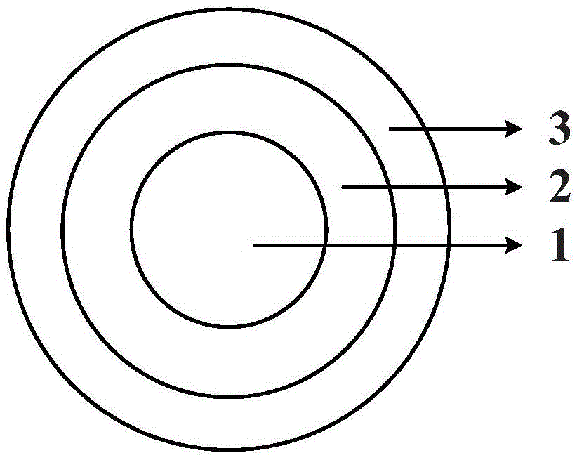
[0063] (1) Using the SH method quasi-isostatic pressing process, the mixture of coated fuel particles and mesophase carbon microspheres is pressed into a spherical shape, and the pressing pressure is 100 MPa to obtain the fuel layer (1);
[0064] (2) Using the quasi-isostatic pressing process again, the fuel layer (1) is pressed into the raw material of the fuel-free layer (2), and the pressing pressure is 100 MPa. The raw material of (2) layer is mesophase carbon microspheres, and the sample (12) is obtained. . And carry out carbonization treatment, the carbonization temperature is 800 ℃. The heating rate is 1°C / min, and the temperature is kept at 800°C for 1 hour.
[0065] (3) Adopting the quasi-isostatic pressing process again, the sample (12) obtained by step (2) is packed into the shell layer (3) raw material, and the (3) layer raw material is 64% natural flake graphite,...
Embodiment 2
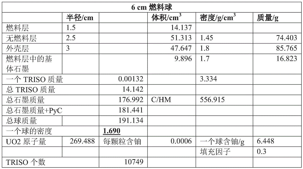
[0067] The fuel element of diameter 6cm that embodiment 2 makes
[0068] With reference to the preparation method of Example 1, a fuel element with a diameter of 6 cm was obtained, and its main parameters are shown in Table 1,
[0069] Table 1
[0070]
[0071] The base materials of the fuel-free layer and the fuel layer in this embodiment are all low-density mesophase carbon microspheres, which have the characteristics of gradual changes in density and thermal conductivity, which can reduce the density of the element body and make it more suitable for molten salt reactors. 2 The layer (no fuel layer) has a thermal conductivity of 35W / mK and a density of 1.45g / cm 3 , 3 layers (shell layer) thermal conductivity is 40W / mK, density is 1.8g / cm 3 .
[0072] At the same time, the average pore diameter of the shell layer is 1 μm, and the compressive strength of the shell layer is 40 MPa. In addition, the preparation process of the fuel layer and the non-fuel layer of the fuel ...
Embodiment 3
[0073] The fuel element of diameter 3cm that embodiment 3 makes
[0074] With reference to the preparation method of Example 1, a fuel element with a diameter of 3 cm was obtained, and its main parameters are shown in Table 2:
[0075] Table 2
[0076]
[0077]
PUM
| Property | Measurement | Unit |
|---|---|---|
| Diameter | aaaaa | aaaaa |
| Bulk density | aaaaa | aaaaa |
| The average particle size | aaaaa | aaaaa |
Abstract
Description
Claims
Application Information
 - R&D
- Intellectual Property
- Life Sciences
- Materials
- Tech Scout
- Unparalleled Data Quality
- Higher Quality Content
- 60% Fewer Hallucinations
Browse by: Latest US Patents, China's latest patents, Technical Efficacy Thesaurus, Application Domain, Technology Topic, Popular Technical Reports.
© 2025 PatSnap. All rights reserved.Legal|Privacy policy|Modern Slavery Act Transparency Statement|Sitemap|About US| Contact US: help@patsnap.com


