Drilling machine with damping and for pushing inner shaft of motor to be fed in pneumatic mode

A technology that promotes motors and drilling machines. It is used in boring/drilling, drilling/drilling equipment, and components of boring machines/drilling machines. It can solve the problems affecting the efficiency of other stations, power loss and noise. It can solve the problems of combined use of the platform, etc., to achieve the effect of simple structure, low manufacturing cost and small space occupation.

Active Publication Date: 2016-11-23
福鼎市金雄机车部件有限公司
View PDF6 Cites 4 Cited by
  • Summary
  • Abstract
  • Description
  • Claims
  • Application Information

AI Technical Summary

Problems solved by technology

[0003] The disadvantage of this structure is that the lifting speed provided by the lifting feed device is a fixed value, and the idle stroke before the drill bit or tap reaches the end of the workpiece is at the same speed as the drilling or tapping operation, and the tool retraction is also at the same speed , but to improve work efficiency, it is required that the idle stroke should be high-speed, and the working condition stroke should be slow
Especially in the automated production line, it will affect the efficiency of other stations
And another kind of known power head is that the traditional mechanical main shaft is driven to rotate by the motor through belt transmission, and the mechanical main shaft is driven by the cylinder to feed and process. The power loss and noise generated in the mechanical transmission process are difficult to get rid of. The center of gravity of the motor is biased toward the end, which requires high rigidity for the clamping and fixing position at the front end, and takes up a lot of space, which is not conducive to the combined use of multiple sets

Method used


Image

  • Drilling machine with damping and for pushing inner shaft of motor to be fed in pneumatic mode
  • Drilling machine with damping and for pushing inner shaft of motor to be fed in pneumatic mode
  • Drilling machine with damping and for pushing inner shaft of motor to be fed in pneumatic mode

Examples


Embodiment Construction

[0028] The content of the present invention will be described in detail below in conjunction with the accompanying drawings and specific embodiments of the description:

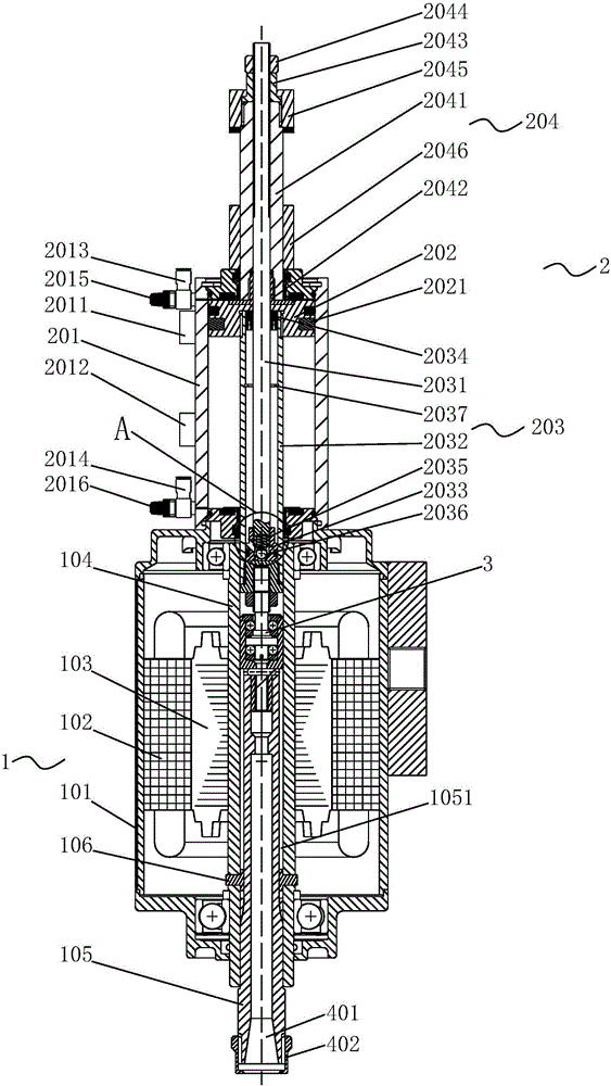
[0029] Such as Figure 1-3 As shown, the present invention provides a drilling machine with a damped pneumatic push motor inner shaft feed, which is characterized in that it includes a motor assembly 1, and the motor assembly 1 includes a The housing 101, the stator 102 fixed in the housing 101, the rotor core 103 movably arranged in the middle of the stator 102, and the motor main shaft arranged in the middle of the rotor core 103; 103 The sleeve body 104 in the central hole and the inner shaft 105 coaxially movably sleeved in the shaft sleeve body 104 body, the two ends of the shaft sleeve body 104 are rotatably connected to the housing 101, and the inner shaft 105 cannot be opposite to each other. The sleeve body 104 rotates but can move axially relative to the sleeve body 104, and the front end of the in...


PUM


Abstract

The invention relates to a drilling machine with damping and for pushing an inner shaft of a motor to be fed in a pneumatic mode. The drilling machine comprises a motor assembly. The motor assembly comprises a shell, a stator, a rotor core and a motor spindle. The motor spindle comprises a spindle sleeve and the inner shaft. The inner shaft cannot rotate relative to the spindle sleeve but can move relative to the spindle sleeve in the axial direction. The front end of the inner shaft stretches out of an end opening of the spindle sleeve and is provided with a connecting component. The drilling machine further comprises a stroke-adjustable damping air cylinder. The stroke-adjustable damping air cylinder comprises an air cylinder body, an air cylinder piston and a damping mechanism. The inner shaft can rotate relative to the damping mechanism but cannot move relative to the damping mechanism in the axial direction. A stroke adjusting mechanism is connected to the rear end of the damping mechanism. By the adoption of the drilling machine, a tool can travel in place at a high speed in the idle stroke, decelerate automatically in the working condition stroke and reset at a high speed in the return stroke, and the working efficiency is improved; the length of the idle stroke and the length of the working condition stroke can be adjusted through the stroke adjusting mechanism, and the application range is wide; and in addition, the structure is simple, the occupied space is small, and the manufacturing cost is low.

Description

technical field [0001] The invention relates to the field of machining equipment, in particular to a drilling machine with a damped pneumatic drive motor inner shaft feed. Background technique [0002] Existing drilling machine, tapping machine are generally made up of frame, squirrel-cage motor, power transmission shaft, lifting sleeve, lifting feed device. The upper end of the transmission shaft is connected to the rear end of the motor shaft through a belt pulley. The transmission shaft and the lifting sleeve are fitted in the form of an inner and outer spline shaft sleeve. A drill chuck is installed at the lower end of the lifting sleeve. The transmission gear of the feeding device is connected by transmission, and the lifting and feeding device drives the transmission gear and the rack to lift through the lifting motor and the gear pair, or directly controls the transmission gear with the handle to implement manual lifting. [0003] The disadvantage of this structure i...

Claims


Application Information

Patent Timeline
Patent Type & Authority Applications(China)
IPC IPC(8): B23B39/00B23B47/00
CPCB23B39/00B23B47/00
Inventor 林雄
Owner 福鼎市金雄机车部件有限公司
Why Eureka
Try Eureka