Magnetic control sintering molding device and method

A technology of sintering molding and magnetic control, applied in ceramic molding machines, manufacturing auxiliary devices, processing and manufacturing, etc., can solve the problems of high specific cost, low strength of formed parts, expensive price, etc., and achieve the effect of low cost and simple forming equipment

Active Publication Date: 2018-05-25
CHINA THREE GORGES UNIV
View PDF4 Cites 0 Cited by
  • Summary
  • Abstract
  • Description
  • Claims
  • Application Information

AI Technical Summary

Problems solved by technology

Although these technologies are mature, each has some problems. For example, the photocuring process is expensive, requires support, resin shrinkage leads to a decrease in precision, and the photocuring resin has certain toxicity problems; the material properties of the layered entity manufacturing process Poor, high cost compared with non-laser technology, lower precision than photocuring process, and complicated equipment; the disadvantage of 3D printing process is that the strength of formed parts is low, and it can only be used for conceptual use, not for functional experiments

Method used


Image

  • Magnetic control sintering molding device and method

Examples


Embodiment Construction

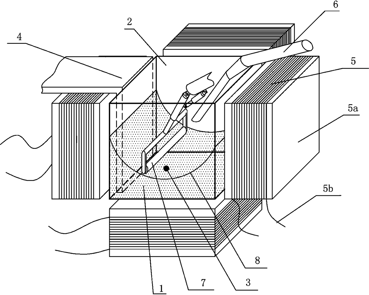
[0030] The present invention will be further described in detail below in conjunction with the accompanying drawings and specific embodiments.

[0031] Such as figure 1 The magnetron sintering molding device shown includes a tank structure 2 for carrying powder 1, a magnetic sphere 3 that is in contact with powder 1 and sinters powder 1, and a pair of magnetic spheres 3 is arranged outside the tank structure 2. An electromagnetic heater 4 for heating, an electromagnet 5 for controlling the movement of the magnetic sphere 3 is installed outside the tank structure 2; an opening for adding powder 1 to the tank structure 2 is also provided Filling device 6; the magnetic sphere 3 is a magnetic ball;

[0032] The tank structure 2 is a cube structure, and its top surface is not closed; the number of the electromagnets 5 is 6, and their installation positions are respectively located on the six sides of the cube of the tank structure 2; One of the two electromagnets 5 facing each ot...


PUM


Abstract

The invention provides a magnetic-control sinter molding device and method. The device comprises a trough structure for containing powder, and a magnetic ball making contact with the powder and sintering the powder. An electromagnetic heater for heating the magnetic ball is arranged outside the trough structure. Electromagnets used for controlling the magnetic ball to move are mounted outside the trough structure. In addition, the invention provides the corresponding magnetic-control sinter molding method. The magnetic-control sinter molding device is simple, low in cost and capable of achieving the purpose of rapid molding without causing environment pollution in the whole sinter molding process.

Description

technical field [0001] The invention relates to the technical field of rapid prototyping, in particular to a magnetron sintering forming device and method. Background technique [0002] At present, the rapid prototyping process mainly includes the following types: 1) Photocuring process: using laser light to continuously irradiate light-cured liquid resin to solidify it; 2) Layered solid manufacturing process: it uses laser cutting foil, and the foil between The hot melt adhesive is melted and bonded under the pressure and heat transfer of the hot pressing roller, and the prototype is manufactured layer by layer; 3) Selective laser sintering process: the laser is used to sinter the powder material point by point, so that the powder material wrapped in the powder material The solid binder or the powder material itself is melted to realize the bonding of the material; 4) 3D printing process: the prototype is made by spraying the binder point by point to bond the powder materia...

Claims


Application Information

Patent Timeline
Patent Type & Authority Patents(China)
IPC IPC(8): B29C64/153B29C64/20B29C64/295B29C64/393B28B1/00B33Y10/00B33Y30/00B33Y50/02C04B35/64
CPCB33Y30/00C04B35/64
Inventor 杨开铭杨晓利安广琳赵俊伟齐俊礼李金刚
Owner CHINA THREE GORGES UNIV
Why Eureka
Try Eureka