Boiler top pasty coal slime inlet structure of circulating fluidized bed boiler

A technology of circulating fluidized bed and coal slime, which is applied in the direction of fluidized bed combustion equipment, burning fuel in molten state, lighting and heating equipment, etc. Reduced utilization rate and other issues, to achieve the effect of simple structure, uniform drop distribution, and less waste of resources

Active Publication Date: 2016-11-23
贵州新能源开发投资股份有限公司
View PDF4 Cites 0 Cited by
  • Summary
  • Abstract
  • Description
  • Claims
  • Application Information

AI Technical Summary

Problems solved by technology

[0002] When coal gangue and coal slime are used for combustion in a circulating fluidized bed boiler at the same time, the coal slime needs to be stirred into a paste by adding water, and then transported to the circulating fluidized bed boiler by a paste pump for combustion, but the existing coal slime After the paste coal slime is produced by the paste pump, the feeding pipe mouth of the circulating fluidized bed boiler has a straight mouth structure. Coal particles of different sizes will be produced in the three-stage coal particle bursting corresponding to the precipitation of components and fixed carbon combustion, resulting in inconsistent residence time, insufficient ignition, insufficient combustion, reduced utilization of coal slime, and great waste of resources

Method used


Image

  • Boiler top pasty coal slime inlet structure of circulating fluidized bed boiler
  • Boiler top pasty coal slime inlet structure of circulating fluidized bed boiler

Examples


Embodiment 1

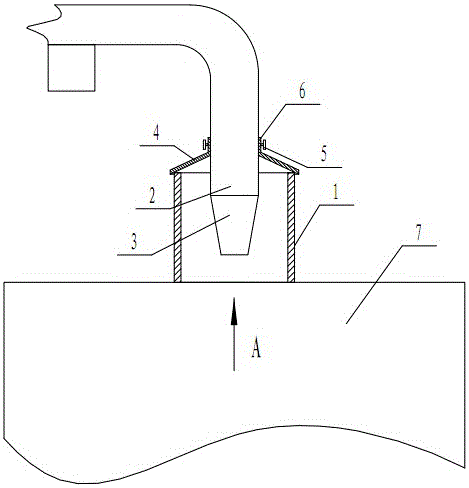
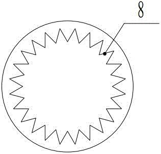
[0016] Embodiment 1: as Figure 1-Figure 2 As shown, a circulating fluidized bed boiler furnace top paste coal slime inlet structure, including the top of the furnace body 7 is provided with a furnace top hole casing 1 and a coal slime inlet insert 2, and the coal slime inlet insert 2 is inserted into the furnace In the top opening casing 1, its end is arranged as a conical part 3 that shrinks downward; the taper of the conical part 3 is 15-20°, and its length is 2-3 of the outer diameter of the coal slime inlet intubation pipe 2. times, through the cone portion of this size, it is beneficial to form the best lump of coal slime, which is more conducive to the combustion in the combustion chamber. The inner side of the lower end of the cone portion 3 is provided with a horizontally directed annular tooth-shaped structure 8, through which the ring-shaped tooth-shaped structure The coal slime group formed at the exit of the ravine is beneficial to drying and burning.

[0017] Pr...


PUM

PropertyMeasurementUnit
Taperaaaaaaaaaa
Thicknessaaaaaaaaaa

Abstract

The invention discloses a boiler top pasty coal slime inlet structure of a circulating fluidized bed boiler. The boiler top pasty coal slime inlet structure of the circulating fluidized bed boiler comprises a boiler top open sleeve and a coal slime inlet insertion pipe. A coal slime inlet insertion pipe is inserted into the boiler top open sleeve. The end of the coal slime inlet insertion pipe is arranged to be a cone portion which is necked downwards. Coal slime is conveyed to the top of the circulating fluidized bed boiler through a paste pump in a high-pressure manner. The coal slime becomes lumps and falls to a fluidized bed naturally. In the falling process of the coal slime, three-level stress bursting is correspondingly formed through drying, volatile matter precipitation and fixed carbon combustion. According to the boiler top pasty coal slime inlet structure of the circulating fluidized bed coiler, because the end of the coal slime inlet insertion pipe is arranged to be the necked cone portion, through a toothed coal slime outlet of the cone portion, the pasty coal slime has better compactness, ditches are formed on the surface of the pasty coal slime through scratching, combustion particles formed through bursting of the coal slime are more uniform in size and falling distribution, and the standing time of the combustion particles is balanced. Therefore, sufficient ignition and complete combustion are better facilitated, the utilization rate of the coal slime is improved, and the combustion loss caused by insufficient combustion of coal slime chunks is avoided. The boiler top pasty coal slime inlet structure further has the advantages of being simple in structure and low in cost.

Description

technical field [0001] The invention relates to a paste coal slime inlet structure at the furnace top of a circulating fluidized bed boiler, and belongs to the technical field of coal gangue and coal slime power generation equipment. Background technique [0002] When coal gangue and coal slime are used for combustion in a circulating fluidized bed boiler at the same time, the coal slime needs to be stirred into a paste by adding water, and then transported to the circulating fluidized bed boiler by a paste pump for combustion, but the existing coal slime After the paste coal slime is produced by the paste pump, the feeding pipe mouth of the circulating fluidized bed boiler has a straight mouth structure. Coal particles of different sizes will be produced in the three-stage coal particle explosion corresponding to the precipitation of components and fixed carbon combustion, resulting in inconsistent residence time, insufficient ignition, insufficient combustion, reduced util...

Claims


Application Information

Patent Timeline
IPC IPC(8): F23C10/22
CPCF23C10/22F23C2206/10
Inventor 刘际均罗宁王志中
Owner 贵州新能源开发投资股份有限公司
Why Eureka
Try Eureka