Measuring Device and method for scattered light

A measuring device and stray light technology, which are used in photoplate-making process exposure devices, optical performance testing, microlithography exposure equipment, etc., can solve problems such as large errors, high requirements for sensor signal-to-noise ratio, and large size effects, etc. Achieve low signal-to-noise ratio, avoid constraints and measurement errors, and improve measurement accuracy

Active Publication Date: 2016-11-23
SHANGHAI MICRO ELECTRONICS EQUIP (GRP) CO LTD
View PDF5 Cites 10 Cited by
  • Summary
  • Abstract
  • Description
  • Claims
  • Application Information

AI Technical Summary

Problems solved by technology

This measurement method has high requirements on the signal-to-noise ratio of the sensor, and the measurement r

Method used


Image

  • Measuring Device and method for scattered light
  • Measuring Device and method for scattered light
  • Measuring Device and method for scattered light

Examples


Embodiment Construction

[0033] Specific embodiments of the present invention will be described in detail below in conjunction with the accompanying drawings.

[0034] The invention proposes a method for indirect measurement of stray light using the relationship between system stray light and phase. Compared with the traditional measurement device, it reduces the requirement for the signal-to-noise ratio of the sensor, improves the measurement accuracy, and avoids the dependence of the exposure measurement method on the process conditions, and can be used for online measurement.

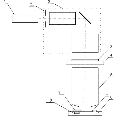
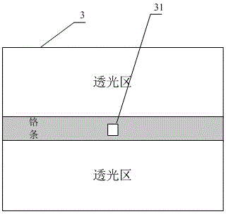
[0035] figure 1 It is a structural schematic diagram of the stray light measuring device involved in the present invention. like figure 1 As shown, the stray light measurement device provided by the present invention includes a light source 1 , an illumination system 2 , an object plane mask 3 , a mask table 4 , a projection objective lens 5 , and a workpiece table 6 arranged in sequence along the optical axis. The illumi...


PUM


Abstract

The invention discloses a measuring device for scattered light. The measuring device is characterized by comprising a light source, a lighting system, a mask table, a workpiece table and a projection lens in the optical axis direction sequentially, wherein the light source is used for providing lighting beams, the lighting system is used for controlling the lighting beams and comprises slit blade edges, a beam shaping element and a dodging element; an object surface test mark plate is arranged on the mask table; an object surface test mark plate, a detector and an energy sensor are arranged on the workpiece table; the detector is used for acquiring shearing interference fringes; the energy sensor is used for measuring reference light intensity; the projection lens can image the object surface test mark plate irradiated by the lighting beams onto the workpiece table; the object surface test mark plate comprises a middle opaque zone and photic zones located on two sides of the opaque zone, and a pore is formed in the opaque zone.

Description

technical field [0001] The invention relates to the field of integrated circuit equipment manufacturing, in particular to a stray light measuring device and a measuring method. Background technique [0002] Among the existing stray light measurement schemes, scheme one is that Kirk et al. propose a detection technique for stray light of the projection objective lens of a lithography machine ("Scattered light in photolithographic lenses", SPIE Vol. 2197, p566-572, 1994), and its work The principle is to set a series of exposure doses according to a certain step length to expose a special mask image, so as to obtain the exposure dose that just removes the photoresist in the non-transparent area and the light-transmissive area on the silicon wafer. The ratio of the two is The required ratio of stray light, but the measurement accuracy of this method is limited, and the required measurement time is longer. [0003] The second scheme is a method proposed by Yao to determine the ...

Claims


Application Information

Patent Timeline
IPC IPC(8): G03F7/20G01M11/02
Inventor 孙昊葛亮
Owner SHANGHAI MICRO ELECTRONICS EQUIP (GRP) CO LTD
Why Eureka
Try Eureka