Flyback power factor correction (PFC) converter with bridge-free structure

A technology of excitation power and converter, applied in the field of flyback power factor correction PFC converter, can solve the problems of large conduction voltage drop of rectifier diode, increase the complexity of control circuit, affect the overall efficiency, etc., and achieve the elimination of current zero-crossing distortion , low cost, and the effect of improving overall efficiency

Inactive Publication Date: 2016-11-23
NANJING UNIV OF SCI & TECH
View PDF3 Cites 3 Cited by
  • Summary
  • Abstract
  • Description
  • Claims
  • Application Information

AI Technical Summary

Problems solved by technology

[0003] Power factor correction PFC belongs to AC-DC conversion. Traditionally, there is a rectifier bridge on the primary side of the isolation transformer, and the diode in the rectifier bridge has a conduction voltage drop. As a result, the current change cannot follow the voltage change when the current crosses zero, resulting in a current zero crossing. Distortion, in order to eliminate the current zero-crossing distortion, it is necessary to add a feedforward link to the control circuit, which great...

Method used


Image

  • Flyback power factor correction (PFC) converter with bridge-free structure
  • Flyback power factor correction (PFC) converter with bridge-free structure
  • Flyback power factor correction (PFC) converter with bridge-free structure

Examples


Embodiment Construction

[0023] In order to better understand the technical content of the present invention, specific embodiments are given together with the attached drawings for description as follows.

[0024] Aspects of the invention are described in this disclosure with reference to the accompanying drawings, which show a number of illustrated embodiments. Embodiments of the present disclosure are not necessarily intended to include all aspects of the invention. It should be understood that the various concepts and embodiments described above, as well as those concepts and embodiments described in more detail below, can be implemented in any of a number of ways, which should be the concepts and embodiments disclosed by the present invention and not Not limited to any implementation. In addition, some aspects of the present disclosure may be used alone or in any suitable combination with other aspects of the present disclosure.

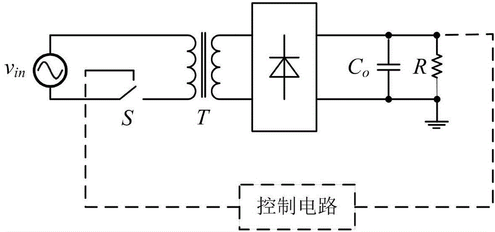
[0025] combine figure 1 As shown, a flyback power factor correct...


PUM


Abstract

The invention provides a flyback power factor correction (PFC) converter without a bridge-free structure. The flyback PFC converter comprises an isolation transformer, a bidirectional switch, a secondary-side diode bridge rectifier circuit, an output capacitor and a load. The bidirectional switch is composed of two switch tubes which are connected in series. The two switch tubes share the same source electrode and the same gate electrode. One end of a voltage source in a main power circuit is connected with any end of the primary side of the isolation transformer. The other end of the primary side of the isolation transformer is connected with any end of the bidirectional switch. The other end of the bidirectional switch is connected with the other end of the voltage source. The secondary side of the isolation transformer is connected with the diode rectifier circuit. The diode rectifier circuit is connected with an energy storage capacitor and the load in parallel. According to the technical scheme of the invention, the flyback PFC converter eliminates the defect of current zero-zero distortion and reduces the conduction loss at the same time. On the premise that the power factor is not changed, the overall efficiency is improved.

Description

technical field [0001] The invention relates to the technical field of power electronics, in particular to a power factor correction technology with low input current harmonics, low voltage output and high efficiency, and in particular to a flyback power factor correction PFC converter with a bridgeless structure. Background technique [0002] In recent years, power electronics technology has developed rapidly, and power supply technology, which is an important part of the power electronics field, has gradually become a hot spot in application and research. Switching power supply has established its mainstream position in the field of power supply due to its high efficiency and high power density, but when connected to different loads, the input current will be distorted, reactive power will be generated, and a large amount of current high-order harmonics will pollute the power grid . There are two main ways to improve the power factor of the power grid. The traditional way...

Claims


Application Information

Patent Timeline
IPC IPC(8): H02M7/217H02M1/42H02M1/12
CPCY02B70/10Y02P80/10
Inventor 陈博洋李磊孙正洋周一帆刘志祥
Owner NANJING UNIV OF SCI & TECH
Why Eureka
Try Eureka