
A non-azeotropic mixed working fluid solution defrosting freezing regeneration large temperature difference heat pump unit

A non-azeotropic mixing, heat pump unit technology, applied in refrigerators, refrigeration components, compressors, etc., can solve the problems of restricting the application of regeneration devices, achieve zero energy consumption for defrosting, improve regeneration efficiency and speed, and achieve good results Effect

Inactive Publication Date: 2018-10-12
NANJING UNIV OF SCI & TECH
View PDF7 Cites 0 Cited by
  • Summary
  • Abstract
  • Description
  • Claims
  • Application Information

AI Technical Summary

Problems solved by technology

After the frosting reaches a certain level, the solution spraying device is turned on. Although its defrosting effect is ideal, the lack of a suitable regeneration device restricts its application.

Method used


Image

  • A non-azeotropic mixed working fluid solution defrosting freezing regeneration large temperature difference heat pump unit
  • A non-azeotropic mixed working fluid solution defrosting freezing regeneration large temperature difference heat pump unit

Examples


Embodiment 1

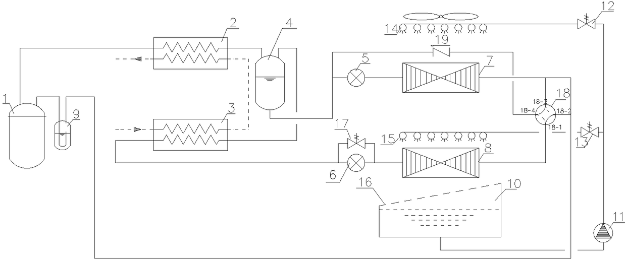
[0025] combine figure 1 The non-azeotropic mixed working fluid solution defrosting and freezing regeneration large temperature difference heat pump unit of the present invention uses the high and low temperature condenser to improve the temperature difference of the heat exchange medium on the secondary side, and uses the low bubble point temperature evaporator as the solution regeneration heat exchanger to remove the heat pump. The frosted dilute solution is frozen for regeneration. The operating modes of the unit are as follows:

[0026] (1) Normal heating operation mode

[0027] The solenoid valve 17 is closed, the 18-3 and 18-4 ports of the four-way reversing valve 18 are connected, and the 18-1 and 18-2 ports are connected. The high-temperature and high-pressure gas at the outlet of compressor 1 first enters the second user-end heat exchanger 2 to condense into gas-liquid two-phase, in which the high-boiling point components are almost completely condensed. The gas-liqui...

Embodiment 2

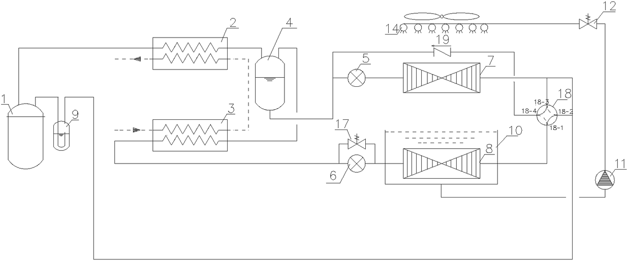
[0035] combine figure 2 The non-azeotropic mixed working fluid solution defrosting and freezing regeneration large temperature difference heat pump unit of the present invention uses the high and low temperature condenser to improve the temperature difference of the heat exchange medium on the secondary side, and uses the low bubble point temperature evaporator as the solution regeneration heat exchanger to remove the heat pump. The frosted dilute solution is frozen for regeneration. The operating modes of the unit are as follows:

[0036] (1) Normal heating operation mode

[0037] The solenoid valve 17 is closed, the 18-3 and 18-4 ports of the four-way reversing valve 18 are connected, and the 18-1 and 18-2 ports are connected. The high-temperature and high-pressure gas at the outlet of the compressor 1 first enters the second user-end heat exchanger 2 and condenses into a gas-liquid two-phase, in which the high-boiling point components are almost completely condensed. Th...


PUM


Abstract

The invention discloses a non-azeotropic mixing working medium solution defrosting refrigeration regeneration large temperature difference heat pump unit which comprises a compressor and a gas-liquid separator with an outlet connected with a suction inlet of the compressor. The unit further comprises a second user side heat exchanger connected with an exhaust opening of the compressor for condensation of a high-boiling point component in a mixed refrigerant, and a fractionator. A gas phase outlet of the fractionator is connected with a first user side heat exchanger for condensation of a condenser rich in low-boiling-point component. A refrigerant outlet of the first user side heat exchanger is connected with a second throttling valve and an electromagnetic valve. After being connected in parallel, the second throttling valve and the electromagnetic valve are connected with an inlet of a solution regeneration heat exchanger. An outlet of the solution regeneration heat exchanger is connected with a first connector of a four-way reversing valve. The high-boiling-point component and the low-boiling-point component in the high-temperature high-pressure non-azeotropic mixing medium are condensed and emit heat at the second user side heat exchanger and the first user side heat exchanger, and large temperature difference heat exchange of the user side heat exchange medium is achieved.

Description

technical field [0001] The invention belongs to the technical field of refrigeration, air conditioning and heat pump, in particular to a non-azeotropic mixed working fluid solution defrosting freezing regeneration large temperature difference heat pump unit. Background technique [0002] In recent years, with the increasing maturity of traditional heat pump technology, the demand for high-temperature hot water for industrial use has increased day by day. However, when the water temperature of traditional air source heat pumps is high, the condensing pressure and exhaust temperature may be too high, which makes the operation of the unit reliable. At the same time, the heating performance of the unit is reduced. The main technical measures currently adopted are to use multi-stage compression, compressor air jet or liquid injection to reduce the exhaust temperature, but the cooling effect of the air jet is not good, and the liquid injection may cause the compressor to be filled...

Claims


Application Information

Patent Timeline
Patent Type & Authority Patents(China)
IPC IPC(8): F25B1/00
CPCF25B1/00F25B2400/06
Inventor 余延顺陈杰曹琳
Owner NANJING UNIV OF SCI & TECH
Learn More