
Connecting prosthesis for bone defects

A prosthesis and backbone technology, applied in the medical field, can solve the problems of slow recovery function, delayed bone healing, pros and cons, etc., and achieve the effects of improving biocompatibility, reducing the weight of the prosthesis, and improving osteogenesis performance

Pending Publication Date: 2016-12-07
佟文
View PDF7 Cites 0 Cited by
  • Summary
  • Abstract
  • Description
  • Claims
  • Application Information

AI Technical Summary

Problems solved by technology

Although the bone defect can be repaired in many ways (such as bone graft joint fusion, artificial prosthesis and traditional allogeneic bone joint transplantation, etc.), each method has its advantages and disadvantages
At present, frozen allogeneic bone joint transplantation is mostly used clinically, but it takes a long time for the bone joint of large allogeneic bone joint transplantation to heal, and some patients do not heal, resulting in nonunion, delayed bone union, allogeneic bone fracture, etc. complication
[0003] Periosteal flaps, autologous bone, artificial bone, etc. are often used for transplantation treatment after fractures of the long shaft bones of the limbs. However, a large number of experiments and clinical studies have proved that simple bone transplantation has disadvantages such as insufficient biomechanical support and bone resorption. Therefore, there is a need for bone implants that can provide biomechanical support
[0004] In the prior art, due to the difficulty in controlling the length of the surgically resected bone segment, it is impossible to properly adjust the prosthesis according to the actual situation during the operation of the prosthesis implantation. As a result, the prosthesis cannot be guaranteed to have good mechanical properties during the installation process, resulting in recovery function is slower

Method used


Image

  • Connecting prosthesis for bone defects
  • Connecting prosthesis for bone defects
  • Connecting prosthesis for bone defects

Examples


Embodiment Construction

[0026] Preferred embodiments of the present invention will be described in detail below in conjunction with the accompanying drawings.

[0027] figure 1 , figure 2 , image 3 , Figure 4 , Figure 5 and Figure 6 Show the specific embodiment of the present invention:

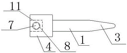
[0028] A connecting prosthesis for bone defects, comprising a fixed prosthesis 1 and an adjusting prosthesis 2, one end of the fixed prosthesis 1 is provided with a connecting part 4, and the other end is provided with a first medullary canal stem that can be inserted into the medullary canal 3. The first medullary canal handle 3 is integrally formed with the fixed prosthesis 1, and the structure is stable. The connecting part 4 is provided with a blind hole 11, and the blind hole 11 is provided with a first positioning hole 7. A positioning hole 7 is provided with a first locking screw 8, one end of the adjustment prosthesis 2 is arranged in the blind hole 11, and is detachably connected with the blind h...


PUM


Abstract

The invention discloses a connecting prosthesis for bone defects and relates to the medical field. The connecting prosthesis comprises a fixed prosthesis body and an adjusting prosthesis body, wherein a connecting component is arranged at one end of the fixed prosthesis body, and a first medullary canal stem is arranged at the other end and is integrally formed with the fixed prosthesis body; a blind hole is formed in the connecting part, a first locating hole is formed in the blind hole, and a first locking screw is arranged at the first locating hole; one end of the adjusting prosthesis body is arranged in the blind hole and detachably connected with the blind hole through the first locking screw, and a second medullary canal stem is arranged at the other end of the adjusting prosthesis body and integrally formed with the adjusting prosthesis body; an adjuster is arranged on the adjusting prosthesis body and can slide on the adjusting prosthesis body, a second locating hole is formed in the adjuster, a second locking screw is arranged at the second locating hole, and the adjuster is detachably connected with the adjusting prosthesis body through the second locking screw. With the adoption of the design, the connecting prosthesis can be adjusted properly according to actual conditions and is enabled to have better mechanical performance and support effect after mounted, and the function can be restored early.

Description

technical field [0001] The invention relates to the medical field, in particular to a connecting prosthesis for bone defects. Background technique [0002] Bone defects after resection of bone tumors, nonunions and defects after fractures of the long shaft bones of limbs are common clinical diseases. How to repair large bone and joint defects caused by bone tumor resection has always been a major problem in orthopedics. Although the bone defect can be repaired by various methods (such as bone graft fusion, artificial prosthesis and traditional allograft bone joint transplantation, etc.), each method has its advantages and disadvantages. At present, frozen allogeneic bone joint transplantation is mostly used clinically, but it takes a long time for the bone joint of large allogeneic bone joint transplantation to heal, and some patients do not heal, resulting in nonunion, delayed bone union, allogeneic bone fracture, etc. complication. [0003] Periosteal flaps, autologous ...

Claims


Application Information

Patent Timeline
IPC IPC(8): A61F2/28A61L27/30A61L27/32
CPCA61F2/28A61F2/2846A61L27/30A61L27/32
Inventor 佟文佟姩
Owner 佟文
Learn More