Air filtering device

An air filter device and space technology, applied in the direction of combined devices, dispersed particle separation, chemical instruments and methods, etc., can solve problems such as poor air filter effect of coolers, potential safety hazards in use, and reduced normal service life of disassembly parts.

Inactive Publication Date: 2016-12-07
慧城(北京)科技有限公司
View PDF5 Cites 1 Cited by
  • Summary
  • Abstract
  • Description
  • Claims
  • Application Information

AI Technical Summary

Problems solved by technology

[0003] The operating environment of my country's high-speed rail is relatively poor. When the cooling fan is working, flocs and other fibers can pass through these layers of filter equipment and directly adhere to the surface of the cooler, resulting in poor heat dissipation performance of the cooler, which leads to a decrease in the temperature of the coolant in the cooling system. If the temperature rises, the train diagnosis system will reduce part of the traction power according to the specific temperature of the coolant, resulting in the speed limit operation of the EMU, and the train diagnosis system will automatically reduce the traction power of the whole vehicle, resulting in the deceleration of the train group, seriously affecting the operation order of the high-speed rail line
[0004] Due to the poor air filtration effect of the cooler of the air conditioning system, in order to solve the problem, the motor vehicle operation department had to disassemble and clean the filter screen every time the motor vehicle enters the warehouse for maintenance. It takes about 2 days to remove the air filter device and clean the surface of the heat exchanger The dirt, the workload is very heavy, and what is even more worrying is the potential safety hazard caused by frequent disassembly and assembly, and the normal service life of the disassembly and assembly parts is reduced.

Method used


Image

  • Air filtering device
  • Air filtering device
  • Air filtering device

Examples


Embodiment Construction

[0025] In order to make the technical means, creative features, goals and effects achieved by the present invention easy to understand, the present invention will be further described below in conjunction with specific embodiments.

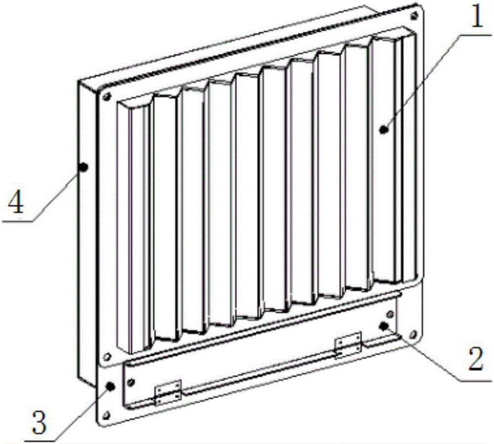
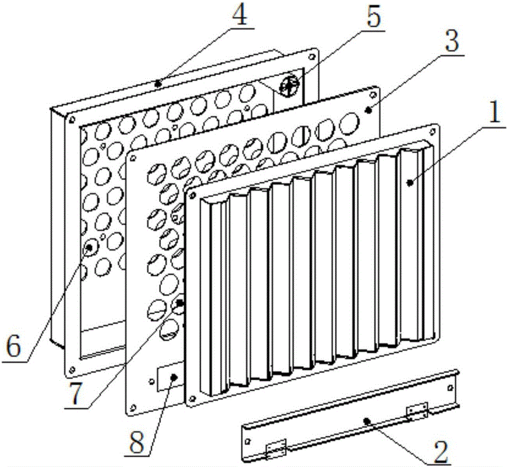
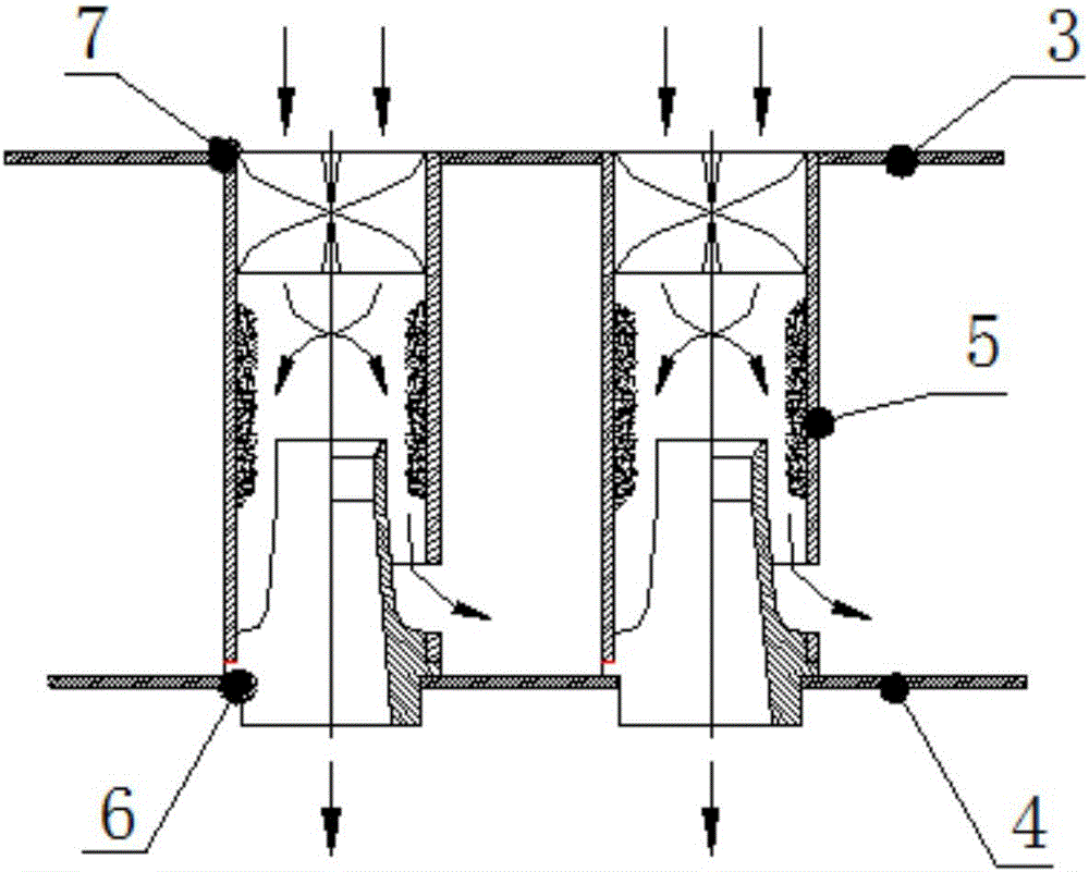
[0026] see Figure 1-Figure 6 , the present invention provides a technical solution: an air filter device, including a V-shaped screen plate 1, a dust discharge cover plate 2, an intermediate plate 3, a box 4, a cyclone pipe 5, a through hole 6, a through hole 7 and a discharge Dust window 8, dust discharge cover 2 is arranged under the V-shaped mesh plate 1, dust discharge cover 2 is fixed on the front end of middle plate 3, dust discharge window 8 is installed on the rear end of dust discharge cover 2, and dust discharge window 8 is assembled on The lower part of the front end of the intermediate plate 3, the rear end of the intermediate plate 3 is provided with a box 4, the rear end of the box 4 is equipped with more than two through holes 6, t...


PUM


Abstract

The invention provides an air filtering device. The air filtering device comprises a V-shaped screen plate, a dust exhaust cover plate, an intermediate plate, a box, cyclone pipes, a dust exhaust window, a dust outlet, a main pipe body, a clean air channel, an air inlet part, a dust exhaust channel, separating space and a cyclone part; the dust exhaust cover plate is arranged below the V-shaped screen plate; the dust exhaust cover plate is fixed to the front end of the intermediate plate; the dust exhaust window is mounted at the rear end of the dust exhaust cover plate, and is assembled at the lower part of the front end of the intermediate plate; the box is arranged at the rear end of the intermediate plate; the V-shaped screen plate is arranged at the front end of the intermediate plate; more than two units of the cyclone pipes are mounted in the box; the lower end of the cyclone part is connected with the separating space; the air inlet part is arranged at the lower end of the separating space; the clean air channel is mounted in the air inlet part; the dust exhaust channel is assembled on the right side of the air inlet part; the lower end of the dust exhaust channel is connected with the dust outlet; the dust outlet is mounted at the lower part of the right end of the main pipe body; air is filtered twice. The air filtering device is convenient to use and operate, high in stability and high in reliability; the filtering effect is improved.

Description

technical field [0001] The invention is an air filter device, which belongs to the field of air filter. Background technique [0002] The electrical equipment and air-conditioning equipment of motor cars, locomotives, and engines of diesel locomotives are important equipment to ensure the normal operation of locomotives. It is required that the air filter device can effectively remove sand and dust particles in the air (such as sand, coal ash, dust, etc.) , moisture and foreign matter (such as poplar catkins, catkins, weeds, etc.), to ensure the cleanliness of the air and the safety of the electrical equipment and engine of the locomotive. [0003] The operating environment of my country's high-speed rail is relatively poor. When the cooling fan is working, flocs and other fibers can pass through these layers of filter equipment and directly adhere to the surface of the cooler, resulting in poor heat dissipation performance of the cooler, which leads to a decrease in the tem...

Claims


Application Information

Patent Timeline
Patent Type & Authority Applications(China)
IPC IPC(8): B01D50/00
CPCB01D50/20
Inventor 程伟喆
Owner 慧城(北京)科技有限公司
Why Eureka
Try Eureka