
Fine positioning magnetic transfer table

A workbench and precise positioning technology, applied in the field of mold manufacturing and precision workpiece processing, can solve the problems of high price, unadjustable Z value height, limited travel distance of tool electrodes, etc., and achieve the effect of low cost.

Active Publication Date: 2018-11-27
DALIAN LUANYI PRECISION ENG
View PDF9 Cites 0 Cited by
  • Summary
  • Abstract
  • Description
  • Claims
  • Application Information

AI Technical Summary

Problems solved by technology

When the number of EDM parts is less than 3000, it is more economically reasonable than die stamping parts; the conventional EDM machine is to install a rectangular permanent magnetic chuck on the marble workbench of the machine tool as the workbench for workpiece processing. Magnetic chucks are generally purchased as standard parts, which are expensive and the height of the Z value cannot be adjusted. For the tool electrode installed on the precision EDM machine, the travel distance is limited, and the head shape of some precision workpieces whose Z value is close to the stroke cannot be used by the precision EDM. For forming machine processing, only ordinary EDM machines with a large stroke can be used, and it is difficult to ensure that the processing accuracy is within ±0.002mm. In addition, if the workpiece is processed by being adsorbed on a rectangular permanent magnetic chuck, coordinate correction is required before processing, and it needs to be corrected after processing. After the workpiece is removed, it is inspected. If the size needs to be corrected, it needs to be installed and corrected again, and then processed again. The secondary processing and positioning will produce cumulative errors that will affect the dimensional accuracy of the workpiece.

Method used


Image

  • Fine positioning magnetic transfer table
  • Fine positioning magnetic transfer table
  • Fine positioning magnetic transfer table

Examples


Embodiment Construction

[0016] Specific embodiments of the invention will be described in detail below in conjunction with technical text and drawings.

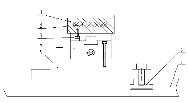
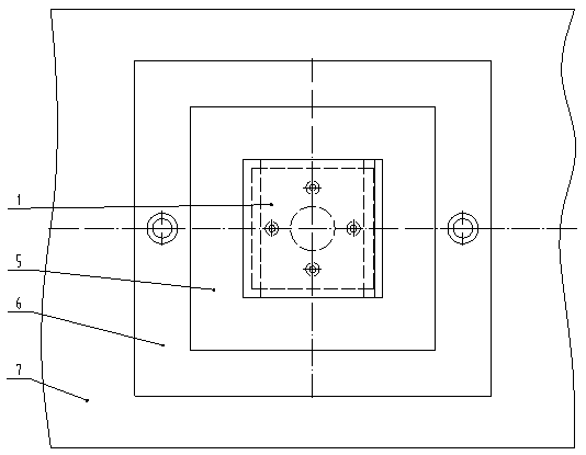
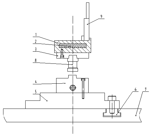
[0017] When assembling the precision-positioned magnetic conversion table, install the powerful magnet 2 in the through hole processed by the conversion table 1 to slide and fit, and contact the conversion table 1 with the chuck 3, and the bolt passes through the chuck 3 to change the table 1 Fixed on the chuck 3 (see Figure 4 ), the reference fixture 4 is in surface contact with the fixture connection plate 5, the bolt passes through the reference fixture 4 to fix it on the fixture connection plate 5, the reference fixture 4 and the fixture connection plate 5 as a whole are in surface contact with the EDM table 7 , The bolt passes through the fixture connecting plate 5 to thread it with the nut 6 set on the EDM table 7 and fix the reference fixture 4 and the fixture connecting plate 5 as a whole on the EDM table 7 (see figure 1 , 3 ), assemble and co...


PUM


Abstract

The invention discloses a fine positioning magnetism conversion workbench, and belongs to the technical field of mold processing and manufacturing. The fine positioning magnetism conversion workbench is structurally characterized by comprising a conversion workbench body 1, a powerful magnet 2, a chuck 3, a datum clamp 4, a clamp connecting plate 5, a nut 6, an electric spark marble table 7, a blind rivet 8 and a workpiece 9. Different heights of the conversion workbench body 1 can be selected according to the height difference of the workpiece 9, and thus the problems existing in the machining process of precision workpieces capable of not approaching the Z-value stroke of an electric spark forming machine on a conventional workbench are solved. The workpiece 9, the conversion workbench body 1 and the chuck 3 are used as a whole for detection and additional machining, secondary alignment of the workpiece 9 for checking the origin of coordinates is avoided, and machining precision and precision of the workpiece 9 are guaranteed. The cost of all the components of the workbench is low, machining is convenient, and manufacturing cost is reduced. The workbench is easy to assemble and convenient to operate, workloads of operators are reduced, and production efficiency is improved.

Description

Technical field [0001] The invention belongs to the technical field of mold processing and manufacturing, relates to a precision positioning magnetic conversion table, and is applied to the processing field of precision workpieces, and is particularly suitable for processing precision workpieces close to the Z-value stroke of an electric spark forming machine. Background technique [0002] EDM is mainly used for the processing of holes and cavities in mold production. It has become the dominant processing method in the mold manufacturing industry and has promoted the technological progress of the mold industry. When the number of EDM parts is less than 3000, it is more economically reasonable than die stamping parts; the conventional EDM machine is to install a rectangular permanent magnet chuck on the marble table of the machine tool as the worktable for workpiece processing. The magnetic chuck is generally expensive to purchase standard parts and the Z height is not adjustable....

Claims


Application Information

Patent Timeline
Patent Type & Authority Patents(China)
IPC IPC(8): B23H11/00
CPCB23H11/003
Inventor 吴东川谭广旭段长春
Owner DALIAN LUANYI PRECISION ENG
Learn More