Processing method of car lamp mold base

A processing method and technology for car lights, which are applied in the field of mold base processing, can solve the problems affecting the accuracy of the mold base, the heat deformation of the mold base, and the complex structure of the mold base, and achieve the effects of simple structure, prevention of excessive deformation, and simple processing procedures.

Active Publication Date: 2018-03-13
宁波龙尚模架科技有限公司
View PDF7 Cites 0 Cited by
  • Summary
  • Abstract
  • Description
  • Claims
  • Application Information

AI Technical Summary

Problems solved by technology

[0003] The cooling system needs to be equipped with a large number of cooling water pipes, in addition to installation holes, positioning holes and ejector holes, etc. A complete set of car lamp molds is assembled from four mold bases, and each assembled mold base Both require multiple hole mechanisms inside. The traditional processing method is to first mill out the original shape of the raw material with a milling cutter, and then use electric spark or electric cutting to punch out the cooling water pipe; however, due to the complex structure of the car lamp, its mold base The structure of the formwork is also very complicated. For example, due to the complexity of the structure on the formwork board, the initial shape is milled first, and then when drilling, some holes will be very close to the wall, which is not easy to punch out, and will damage the wall. In addition, because the initial shape is milled first, and then drilled, the number of holes is large, which can easily lead to thermal deformation of the mold base, thus affecting the accuracy of the overall mold base

Method used


Image

  • Processing method of car lamp mold base

Examples


Embodiment Construction

[0020] Below in conjunction with embodiment the present invention is further described in detail. It should be pointed out that the following specific descriptions are all exemplary, and are intended to provide further description of the present invention. Unless otherwise specified, all scientific and technical terms used in this invention have the same meaning as commonly understood by those skilled in the art to which this invention belongs.

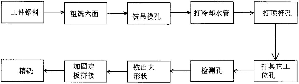
[0021] as attached figure 1 As shown, a method for processing a car lamp mold base of the present invention, the method includes: sawing the workpiece, rough milling six sides, milling the hanging mold hole, drilling the cooling water pipe, drilling the ejector pin hole, drilling other station holes, testing Holes, milling out large shapes, splicing with fixed plates, fine milling;

[0022] The workpiece sawing material is according to the size of the drawing and the machining allowance of each process is reserved. The specific mach...


PUM

PropertyMeasurementUnit
thicknessaaaaaaaaaa

Abstract

A machining method of an automobile lamp mold frame is characterized by comprising the steps of workpiece sawing, six-face rough milling, punching of a cooling water tube, punching of an ejecting rod hole, punching of other station holes, detecting of holes, large shape milling, splicing of a fixing plate, and finish milling. A plate material is milled first and then the hole drilling process of the cooling water tube is directly conducted. The structure of the plate material is simple, the six faces of the plate material are flat and smooth, the hole drilling process of the cooling water tube is convenient and fast to conduct, and the phenomenon that a wall face is damaged or abraded during hole punching due to the fact that the distance between the wall faces of staggered and rugged wall-shaped structures obtained by milling a large shape first and holes to be punched is avoided. More importantly, the cooling water tube and other holes are punched first, then the machining processes of large shape milling and finish milling are conducted. The plate material is milled first, the material is regular in structure, even multiple holes are machined in the material, the small deformation performance of the whole section material can be still guaranteed, the standard size of a formwork can be effectively guaranteed, and over deformation is prevented.

Description

technical field [0001] The invention relates to the technical field of mold base processing, in particular to a processing method for a vehicle lamp mold base. Background technique [0002] The mold base is a semi-finished product of the mold. It is composed of various steel plates and matching parts. It can be said that it is the skeleton of the whole set of molds. be valued. With the continuous growth of the automobile market, the shape and performance requirements of automobile lights are becoming more and more abundant and strict. However, most of the automobile lights are plastic products, and the main processing technology used is injection molding. Therefore, a good formwork structure design It is the prerequisite for the manufacture of a qualified injection molding product. The mold base structure and product structure need to be analyzed in all aspects, such as including: mold release slope, product surface miniature, gating system design, exhaust system design, co...

Claims


Application Information

Patent Timeline
Patent Type & Authority Patents(China)
IPC IPC(8): B23P15/00
CPCB23P15/00
Inventor 丁全福柯友邦李依娜
Owner 宁波龙尚模架科技有限公司
Why Eureka
Try Eureka